MS-6-P-2660 Application of Atomic Force Microscopy in Morphology Characterization of Industrial Polymers
Atomic force microscopy (AFM) has emerged as a key microscopy tool for the characterization of the morphology of multiphase polymer systems with the development of AFM tapping mode height and phase imaging. In this abstract, we highlight the development and the benefits of morphology studies by AFM on variety of key industrial polymer multiphase systems containing hard and soft components.
First we demonstrate that AFM offers significant safety (no staining requirement) and productivity (no need for thin-sections) benefits over TEM while achieving similar resolution for the complete morphology characterization of polycarbonate (PC) / Styrene-acrylonitrile (SAN) / Acrylonitrile-butadiene-styrene (ABS) rubber materials (Figure 1). After this initial application of AFM in PC/SAN/ABS, new methods based on using a combination of AFM and image analysis are developed for the quantitative morphology characterization of PC-siloxane copolymer materials to further understand the influence of morphology on the materials aesthetic properties. As shown in Figure 2, conventional TEM approach can provide morphology images of PC-siloxane copolymer materials. However, performing accurate quantitative image analysis on these TEM images proves very challenging due to the lack of a strongly defined contrast between the siloxane domains and the PC phase. Using AFM in tapping mode, an enhanced contrast between siloxane and the PC phase (Figure 2) is generated vs. TEM. This high contrast morphology imaging enables accurate quantitative morphology studies on both the siloxane domain size distribution and the siloxane domain dispersion in a variety of PC-siloxane copolymers. The results of these quantitative morphology studies provide insight into the relationship between the material structure and its properties and significantly support further improvements in materials properties.
In the case of PC / Polybutylene Terephthalate (PBT) polymer blends containing saturated impact mordifiers (IMs), AFM in combination with TEM provides a complete morphology evaluation of the material. TEM imaging provides a high contrast between the PC and PBT phases via differential staining. However, as saturated IMs cannot be stained with the common staining techniques, they typically appear as white particles in the PBT phase in TEM images. AFM phase imaging provides a significant improvement in the contrast between the IM and the PC/PBT matrix. The high contrast of IMs in the AFM images allows us to perform quantitative analysis of IMs size distribution to further understand the influence of processing conditions on the material morphology and properties (Figure 3) and to further fine-tune the properties of these materials by dialing into specific processing conditions.
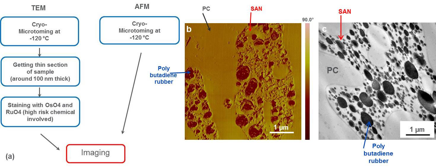
Fig. 1: Figure 1. (a) TEM and AFM sample preparation procedures for general impact modifier contained polymer system. (b) AFM phase images and (c) TEM image of polymer blends (PC/SAN/ABS HRG). Different components as indicated in the images: PC is the continuous phase, SAN is in the PC matrix, and polybutadiene rubber is dispersed in SAN. |
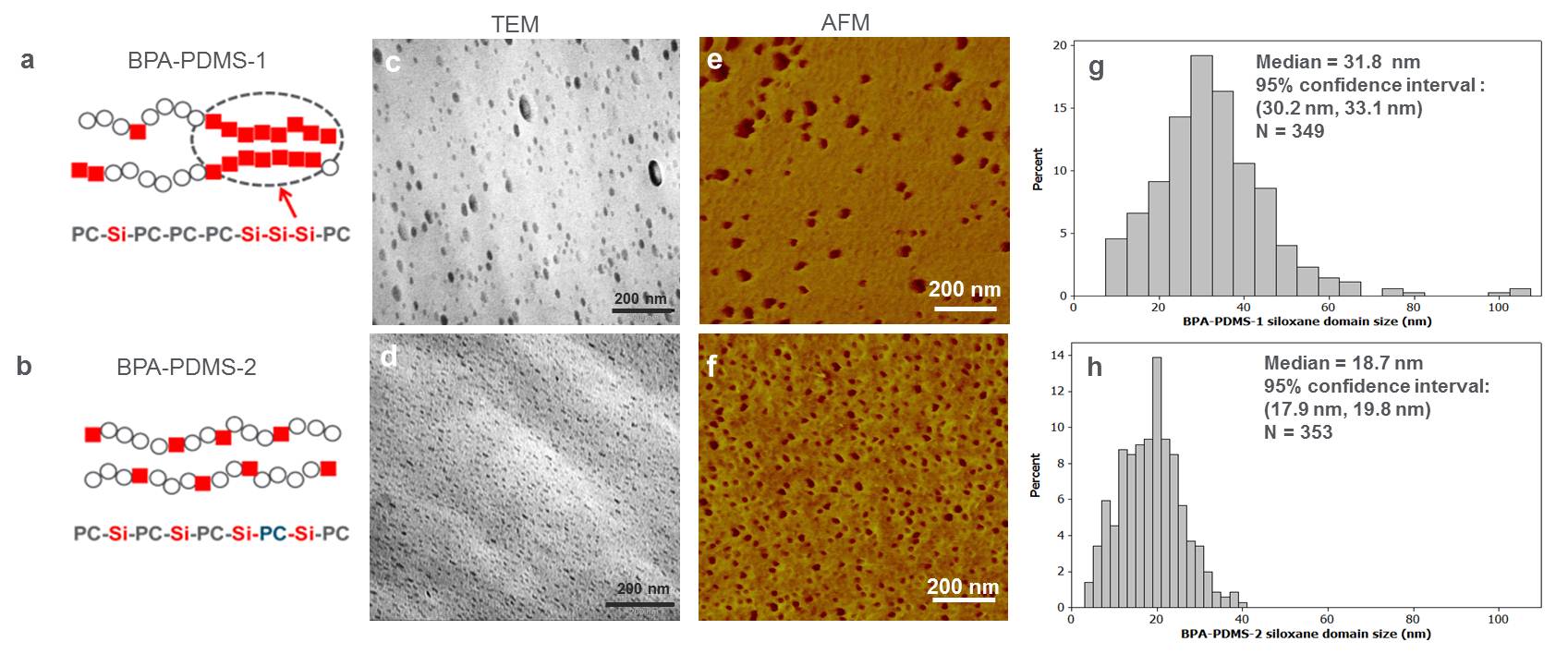
Fig. 2: Figure 2. Chainarchitecture of opaque PC-siloxane copolymer (BPA-PDMS-1) (a) and transparent PC-siloxanecopolymer (BPA-PDMS-2) (b). Morphology of “BPA-PDMS-1” by TEM (c) and AFMtapping mode imaging (e) and siloxane size distribution (g). Morphology of “BPA-PDMS-2” by TEM (d) and AFMtapping mode imaging (f) and siloxane size distribution (h). |
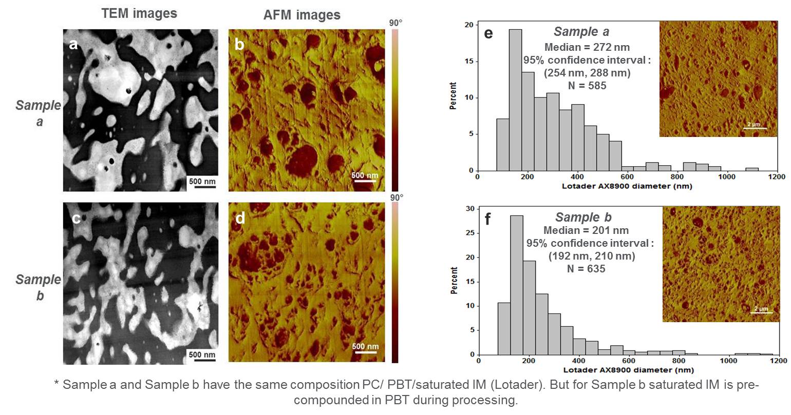
Fig. 3: Figure3. TEM (a & c) and AFM (b & d) phaseimages of PC/PBT blends containing saturated IM. TEM images show thePC/PBT matrix but the saturated IM Lotader† shows unclear contrast. AFM phase images show the morphology ofLotader† IM as darker phase. (e) and (f) Lotader† IM domain sizedistribution and median particle size of sample a and b. |
|