MS-4-O-2559 Atomic resolution investigation of twin boundaries in Fe-Cr-Mn austenitic TWIP steels with aberration-corrected transmission electron microscopy and real-space strain field calculation
The development of austenitic stainless Fe-Cr-Mn-steels alloyed with carbon and nitrogen was shown to result in an increased strength with good plasticity and toughness at the same time [1]. Adding Mn as an austenite stabilizer decreases the stacking-fault energy (SFE) in the steel, which favors mechanical twinning over dislocation glide. The strain-hardening of TWIP steels is commonly attributed to the formation of deformation twins, as twin interfaces act as strong obstacles to dislocation glide. This effect is consequently controlled by interaction of perfect and partial dislocations with twin boundaries and twinning kinetics [2]. In this investigation, an austenitic steel with the chemical composition of Fe–14 wt.% Cr –16% Mn–0.3% C–0.3% N was studied after tensile deformation to 1 and 20 % strain. Detailed microstructural properties were observed by high resolution TEM (HRTEM) and Scanning TEM (STEM) by utilizing image and probe-corrected FEI Titan microscopes.
Figure 1 exhibits the formation of two different deformation twins systems active in the same grain for 20% strain. The diffraction pattern (inset of Fig. 1) clarifies that the twin boundaries are parallel to the (111) plane. The same area investigated by HRTEM clearly shows the atomic arrangement in the twin boundary (see Fig. 2). In this image the grain was tilted to the [011] zone axis. In order to interpret the images obtained by HRTEM, they were used as a basis for the reliable measurement of atomic distances at the twin boundary or in the neighboring matrix area. The precise atomic column positions were calculated with the imTools software package. These coordinates were used as input for further real space structure analysis and calculation of the displacement field and the strain field in the twin boundaries. Figure 3 shows the real space analysis of a twin boundary which used to obtain precise atom coordinates in the twin boundary. Using the coordinates, the displacement vector and its magnitude were calculated. The strain field in the twin boundary was also calculated by different approaches and the implications for the materials properties will be discussed.
Refrences:
[1] H. berns, V.G. Gavriljuk, S. Riedner, and A. Tyshchenko: Steel Res Int 78, 9, 2007, P. 714
[2] T.-H. Lee, C.-S. Oh, S.-J. Kim, S. Takaki, Acta Materialia 55, 2007, P. 3649
Authors would like to acknowledge Dr. Lothar Huben for his technical advice on working with imTools and the SFB 761 “Steel –ab initio” for financial support of this work.

Fig. 1: Bright Field image of twins and stacking faults after 20% deformation exhibiting two sets of active twins. |
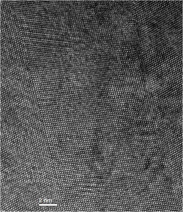
Fig. 2: High Resolution TEM image of a ca. 10 nm wide twin after 20% deformation |
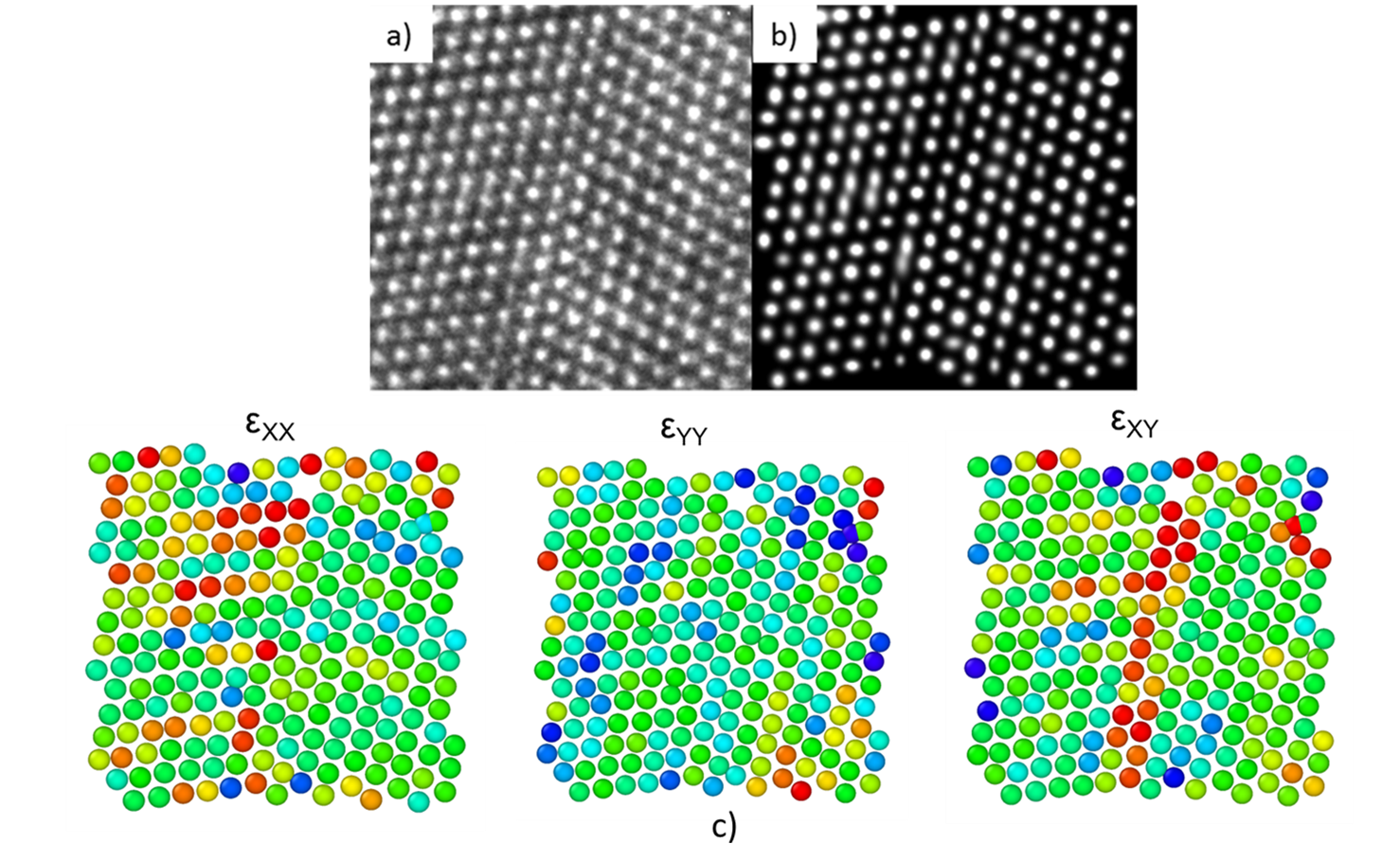
Fig. 3: a) enlarged section of the HRTEM image of a twin boundary in Fig. 2, b) the real space analysis used to calculate atomic coordinates. From these coordinates, c) strain fields are calculated at the twin boundary and in its vicinity. |
|