IT-10-P-3455 Use your smartphone to calibrate your TEM's goniometer
For reconstruction of tomographic data sets the precise knowledge of the experimental parameters is mandatory. Besides the incident intensity [1], the tilt angles have to be known precisely. In a recent paper, Hayashida and co-workers [2] measured the accuracy of a TEM goniometer and found a total deviation of 4° over an angular range of about 180°. This shows that the goniometer might be a source of flawed input data with serious consequences for the reconstruction work. Thus, calibrating the TEM's goniometer can be essential for high quality tomography work.
For calibration, a digital protractor can be used[2]. However, smartphones provide a number of sensors, among them accelerometers.
To determine the tilting accuracy of our LIBRA 200 FE TEM the acceleration sensors were used. An android application was written which reads out the acceleration raw data along the SP´s x-, y-, z-axis and stores it to a file.
While orienting the SP such that two axes show zero acceleration, the third axis is expected to be parallel to the earth´s gravity field vector. In these positions accelerations different from 9.81 m/s² where found. As a first approach, we slowly rotated the device to find for each axis the maximum and minimum acceleration value and used this pair to linearly scale the reading to the interval [-1,1]. In a second step, the three component acceleration vector was normalized to length 1.0 g (= 9.81 m/s²).
To measure the tilting angles of the TEM, the SP was mounted on a Fischione (model 2040) tomography holder. A self written script within Gatan´s Digital Micrograph was used to tilt the holder from -76° to 76° with 1° increments. Each tilting step was followed by a 10 seconds rest.
The acquired data set was processed as outlined above resulting in a stepped curve (tilt versus time).
The difference between the measured and the set value is plotted in Fig. 1.
An error with a periodicity of about 15° of the goniometer's worm gear is evident. However, whereas the reproducibility within each group is very good, an offset is observed between the groups which we attribute to a insufficient calibration of the accelerometers.
Nevertheless the sensitivity of the sensors turns out to be enough to detect tilting deviations significantly smaller than 0.1°. Therefore, we aim at improving the sensor calibration. This will allow for precise calibration of the goniometer.
References
[1] Wollgarten, M., Habeck, M., Micron, in print, doi: 10.1016/j.micron.2014.02.005 (2014).
[2] Hayashida, M., Terauchi, S., Fujimoto, T., Rev. Sci. Instrum. 82, 103706, doi: 10.1063/1.3650457 (2011).
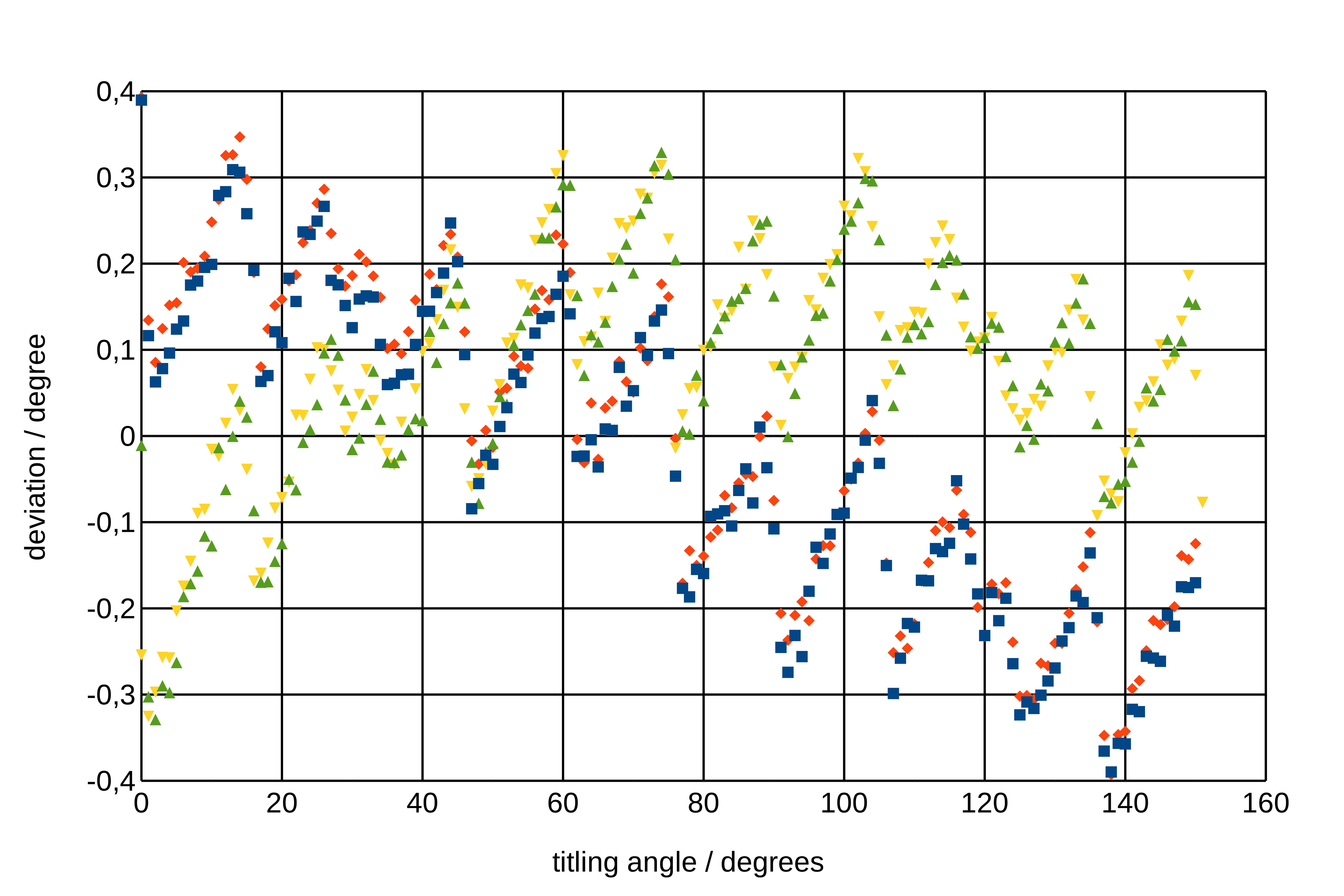
Fig. 1: Measured deviation from the nominal goniometer tilt angle. The squared markers represent the configuration for which the smartphone was vertically mounted at a nominal tilt of zero degree. For the other set it was fixed in horizontal orientation. |