IT-9-O-3245 Pushing the boundaries of symmetry determination with ‘digital’ electron diffraction
The symmetries in convergent beam electron diffraction (CBED) patterns and their relationship to crystal space groups were first explained almost 40 years ago, and there have been many investigations which have used this to solve crystal structures. The utility of CBED lies in the ability to obtain patterns from regions only a few nm in size, well below that attainable by other methods, sampling perfect crystal that is unaffected by defects or domain structure. Nevertheless, the technique is restricted by small Bragg angles, making it difficult or impossible to apply to materials with closely-spaced spots in a diffraction pattern. Use of computer control to collect patterns at different incidence angles is now relatively straightforward and overcomes this limitation. Capture of many hundreds or thousands of CBED patterns allows reconstruction of ‘digital’ large-angle CBED (D-LACBED) patterns from regions only a few nm in size. The vast increase in information allows previously intractable problems of symmetry determination – particularly for materials with lattice parameters >1nm – to be solved with relative ease. We give several examples, including AgNb7O18, Ca2Mn3O7, polarity measurements in thin PZT films, and polar nanodomains in Na0.5Bi0.5TiO3.
Figure 1 shows [001] diffraction patterns from AgNb7O18. X-ray diffraction showed the material to be orthorhombic with lattice parameters a = 1.4331, b = 2.6151 and c= 0.3836 nm, but was unable to distinguish between four possible space groups: I222, I212121, Imm2 and Immm. Selected reflections from the corresponding D-LACBED pattern, a combination of 2600 CBED patterns, are shown in Fig. 1b. The whole pattern has a vertical mirror but not a horizontal mirror. Opposing dark field patterns with ±g vectors are not equivalent when translated onto each other, demonstrating that the crystal structure is acentric and eliminating the space group Immm. The projection diffraction group of the pattern is therefore m1R, which fixes the point group as mm2. This is consistent with dielectric permittivity measurements which show that is AgNb7O18 is an ergodic relaxor ferroelectric.
Data from, the Ruddlesden-Popper phase Ca2Mn3O7, is shown in Fig. 2. Occasional stacking faults are visible in the HREM image (Fig. 2a) and these were avoided in the collection of D-LACBED patterns. Again, X-ray diffraction is able to limit the possible space groups to a small number of possibilities, in this case Cmcm or Cmc21. The spacing between spots in the SAED pattern (Fig. 2b) is such that no detail is visible in CBED patterns (Fig. 2c). The D-LACBED pattern projection diffraction group is m1R, indicating the lack of a centre of symmetry and confirming the space group to be Cmc21.
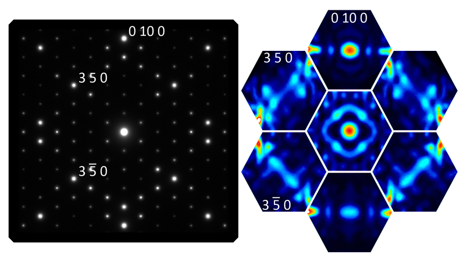
Fig. 1: Fig 1. (a) SAED pattern from [001] AgNb7O18. (b) D-LACBED patterns showing a vertical mirror, no horizontal mirror, and acentricity (projection diffraction group m1R). |
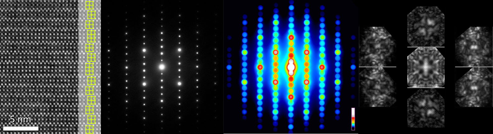
Fig. 2: Fig 2. [001] Ca2Mn3O7. (a) HREM image of stacking faults; (b) SAED and (c) CBED patterns, (d) selected D-LACBED patterns (projection diffraction group m1R) |