IT-1-P-3222 Contrast enhancement in TEM imaging by use of a central beam stop
In TEM in life science, beam damage is the most important limitation. This is also the case for materials science samples like graphene, polymers and hybrid materials. On the imaging side an important boost is expected from the introduction of a phase plate. Phase plates have been researched over several decades and no easy to use system has emerged yet, indicating that is not easy task. Given the importance of efficient imaging, it is clearly necessary to explore other routes. We have explored [1] the possibility of dark-field imaging for contrast enhancement in which we have tried to block the central beam [2] and leave as many of the diffraction beams un-blocked.
Central beam block apertures (the abbreviation DF-000 is used in this abstract) in the shape of Mercedes star (see Figure 1) were made with a FIB. In our experiments we have observed no sign of charging, possibly due to the DF-000 shape. In central disk should preferably be smaller than the frequency, g, one wants to observe, which is of course much smaller for biological samples than for most materials samples. Our DF-000 removed frequencies corresponding to d-spacings of 8.7 Å and larger. In the presentation we will report how far we can decrease the size of central disk without charging problems and with still good blocking of the central beam.
For the drilling of holes in exfoliated graphene without contamination build-up we heated the graphene to 600°C. TEM experiments were done at 300keV and post-specimen aberration correction at 600°C. Figure 1c and 1d shows high-resolution and DF-000 images of multilayer graphene (4-5 layers). A hole was made in this sample using an e-beam. This hole can be seen very well in the DF-000 image and only faintly in the BF image. In both cases one can see that the graphene lattice continues up to the edge of the hole. The gradual decrease in thickness is clearly visible in the DF-000 image and not at all in the BF image. Thus we can obtain in the DF-000 image high-resolution information with a similar resolution limit as the BF image.
Figure 2 shows several images of graphene with three holes with varying size imaged at various focus values, showing that the bright field images in the range from -1500 to + 1500 nm show hardly any contrast and none at zero focus. On the contrary, the contrast in the DF-000 taken at 0 focus shows the largest contrast and in particular the smallest delocalization. In this case selecting ~ zero focus is easy by minimizing the blurring in the image.
1. Zhang C, Xu, Q, Peters PJ, and Zandbergen, H, Ultramicroscopy 134, 200 (2013)
2. Cowley, J., Acta Crystallographica Section A 1973, 29, 529-536
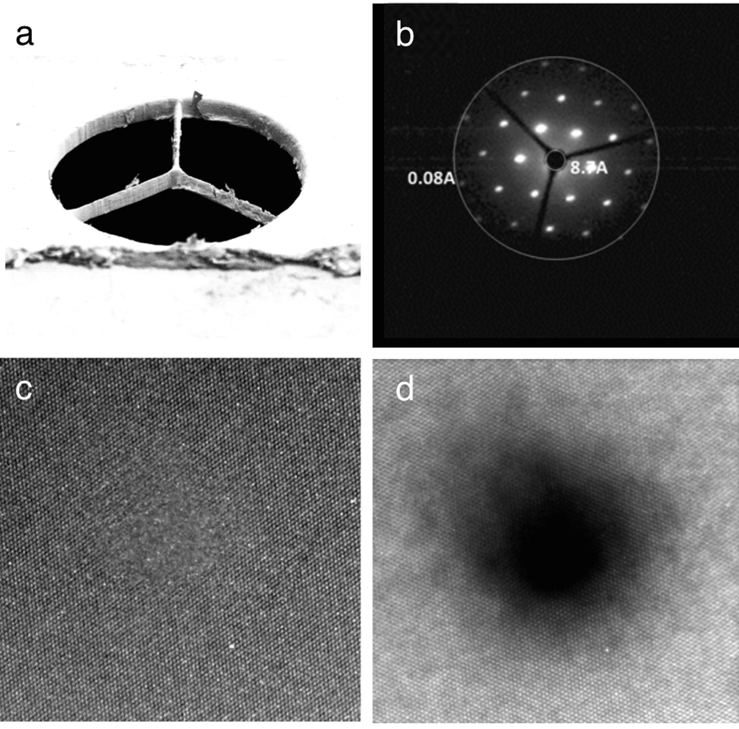
Fig. 1: (a) SEM image of the DF-000 objective aperture used to stop the central beam. (b) shows a typical DF-000 aperture in diffraction space. (c) and (d) show HREM images taken without an aperture and with the DF-000 image taken from the exactly the same area. |
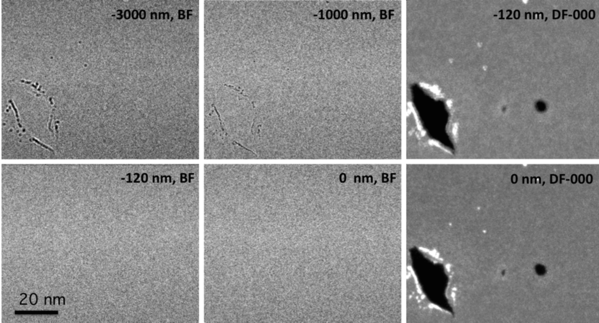
Fig. 2: Images from the same area of single layer graphene with three holes showing the effect of focus in BF and in DF-000 modes. No DF-000 at defocus values of -1000 and -3000 nm are given because these are too blurred. The two small holes are only barely visible in the BF image taken at -3000 nm and not at all in the other three BF images. |