IT-4-P-3156 Microflow and Thermal Control System Design for Wet Cell in the Scanning Electron Microscope
Scanning Electron Microscope has been widely used in different scientific areas such as material analysis, biology and life science. SEM integrated with a wet cell was proposed in recent years to satisfy the needs from live cell imaging. In the SEM, it requires a vacuum chamber to allow the operation of the electron beam and to minimize the scattering from other sources. To extend the ability of live cell observation in the SEM, the Si3N4 thin film supported by silicon microchip was developed in order to cultivate biological materials in the wet cell. Therefore, the wet cell can be used to visualize live tissues in fully hydrated conditions and to maintain the culture environment. It would be particularly valuable when applying to the analysis of lipid membranes in cells as they are difficult to preserve during dehydration and washing steps. The processes of sample preparation can be more efficient by using the wet cell. Furthermore, with the continuous flow control and real-time monitoring, the long-term operation can be achieved and also expand the applications of the wet cell.
In Fig. 1, it shows the meshes of simulation model in the wet cell. The pressure is critical because the flowrate needs to be well maintained in order not to break the thin film. To increase the flowrate and reduce the costs of the fluid mechanics, the geometry and flow conditions were optimized based on the skills of Design Of Experiments. The resulting pressure on the 50 nm thin film was simulated by CFD software (ANSYS Fluent v14) and the results are shown in Fig. 2. It demonstrates that the inlet flowrate still could be raised and the size of the wet cell can be reduced. With regard to the thermal control system, a preheating system of buffer liquid was developed by using a thermal control module. In addition to preheating system for the buffer liquid, an embedded micro thermal control element was also designed inside the wet cell with the capability of fine-tuning so as to achieve accurate and rapid temperature control. Furthermore, several design parameters including noiseless, non-vibration and long working life were also considered for the thermal control system. After preliminary experiments, the results are shown in Fig. 3. and the heating rate inside the wet cell can be achieved to 3.7 ℃ per minute. Eventually, the microflow and thermal control systems were integrated and the system architecture is shown as Fig. 4. With the microflow and thermal control modules integrated in the SEM, the flowrate and fluid temperature can be adjusted by users and the flow conditions including temperature, pressure and even the fluid properties can be simultaneously monitored as well.
Thanks for the technical assistance and suggestions from R&D team of Taiwan Electron Microscope Instrument Corporation (TEMIC) during system integration.
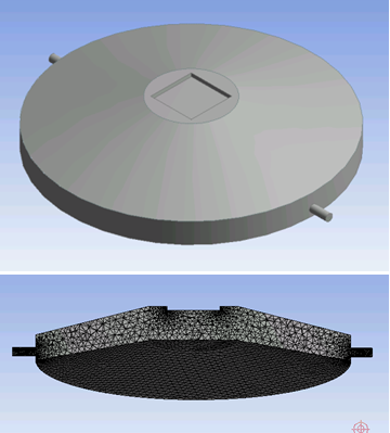
Fig. 1: Meshes of the liquid volume inside the wet cell |
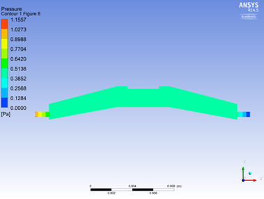
Fig. 2: The pressure on the thin film inside the wet cell |
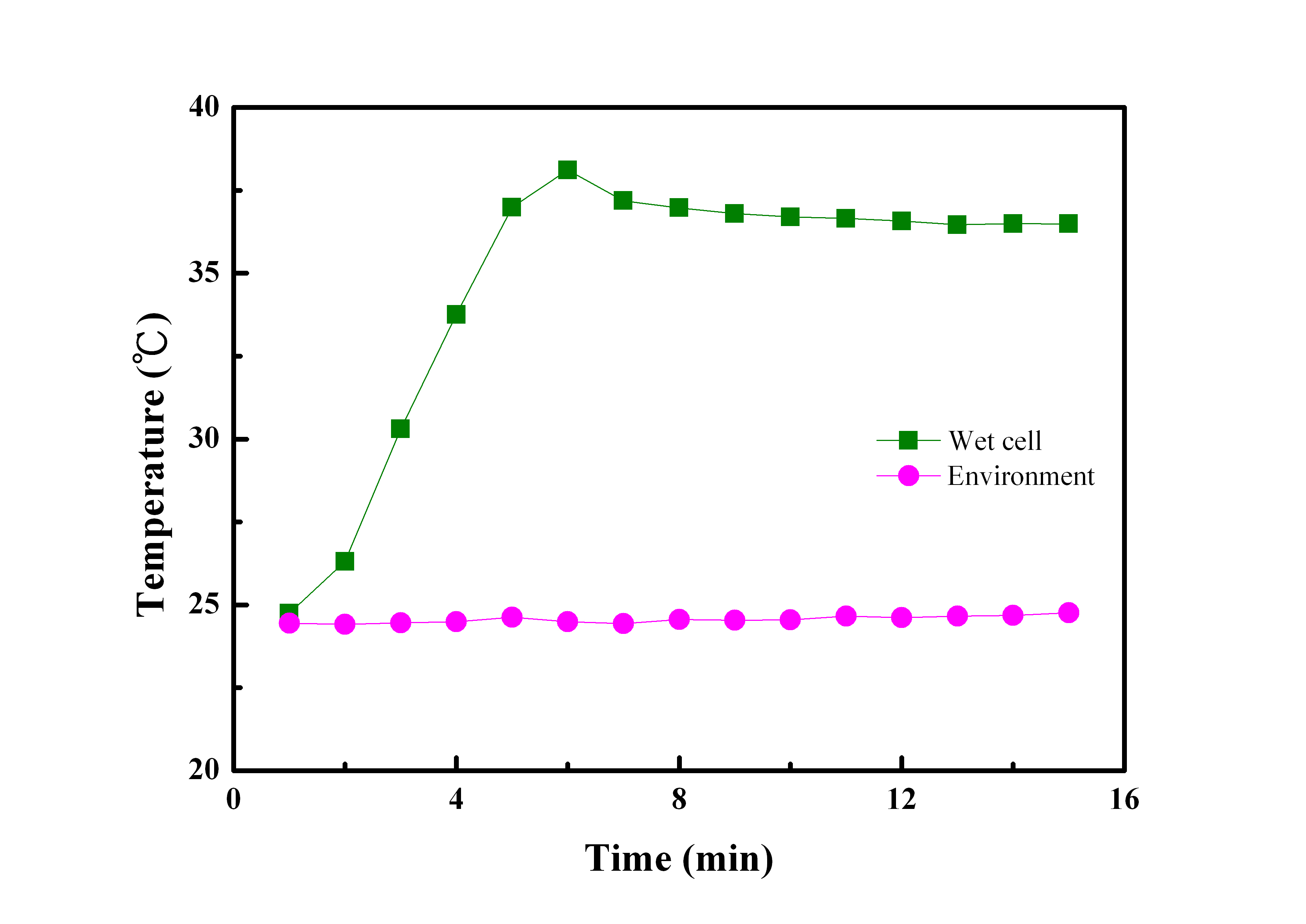
Fig. 3: The temperature variation in the wet cell during heating process |
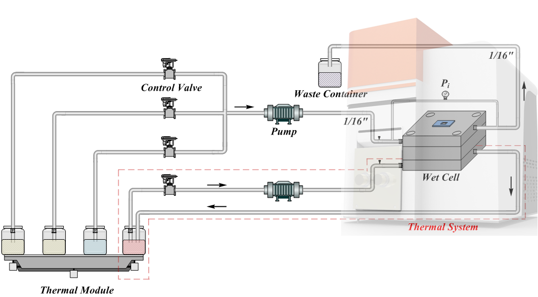
Fig. 4: System architecture of microflow and thermal control system |