IT-1-P-3022 Measuring the Orbital Angular Momentum of Electron Vortex Beams by Forked Grating
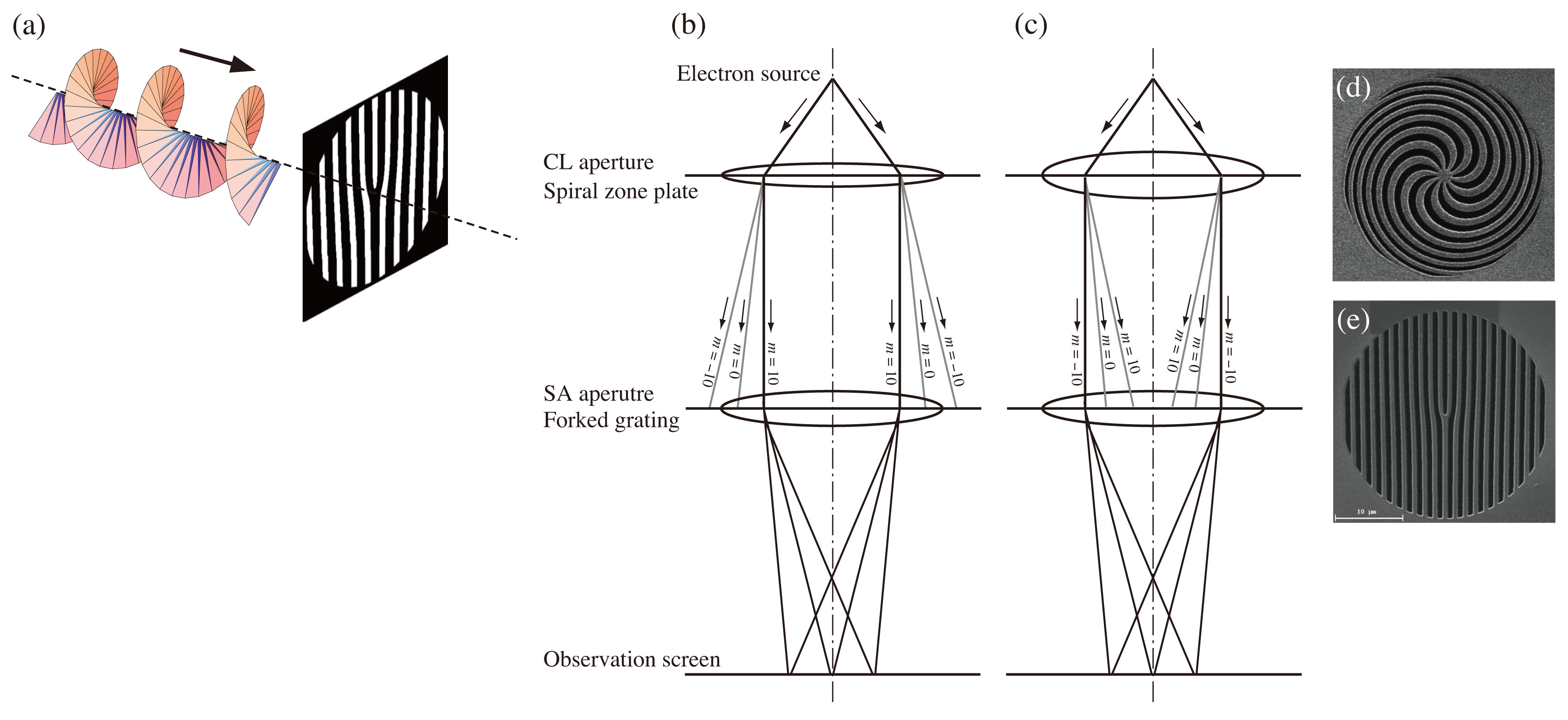
After the first report of the production of an electron vortex beam, an electron traveling in free space with orbital angular momentum (OAM) [1], electron vortex beams have been attracting a great attention owing to the unique physical property and application to a new microscopy in materials science [2]. In the present paper, we show the how the electron vortex beams are diffracted by forked gratings and how the OAMs of the electron vortex beams are transferred to each of the diffracted waves (Fig.1(a)). [3].
Figures 1(b) and 1(c) show a schematic diagram of the experimental setup of the present study. The binary masks of the spiral zone plates [Fig. 1(d)] and the forked gratings [Fig. 1(e)], fabricated from 200 nm thick PtPd films using a focused-ion-beam instrument (Hitachi FB-2100). The spiral zone plates and forked gratings were inserted into the condenser lens aperture position and selected-area aperture position, respectively, of a transmission electron microscope (JEOL JEM-2100F), which was operated at an acceleration voltage of 200 keV.
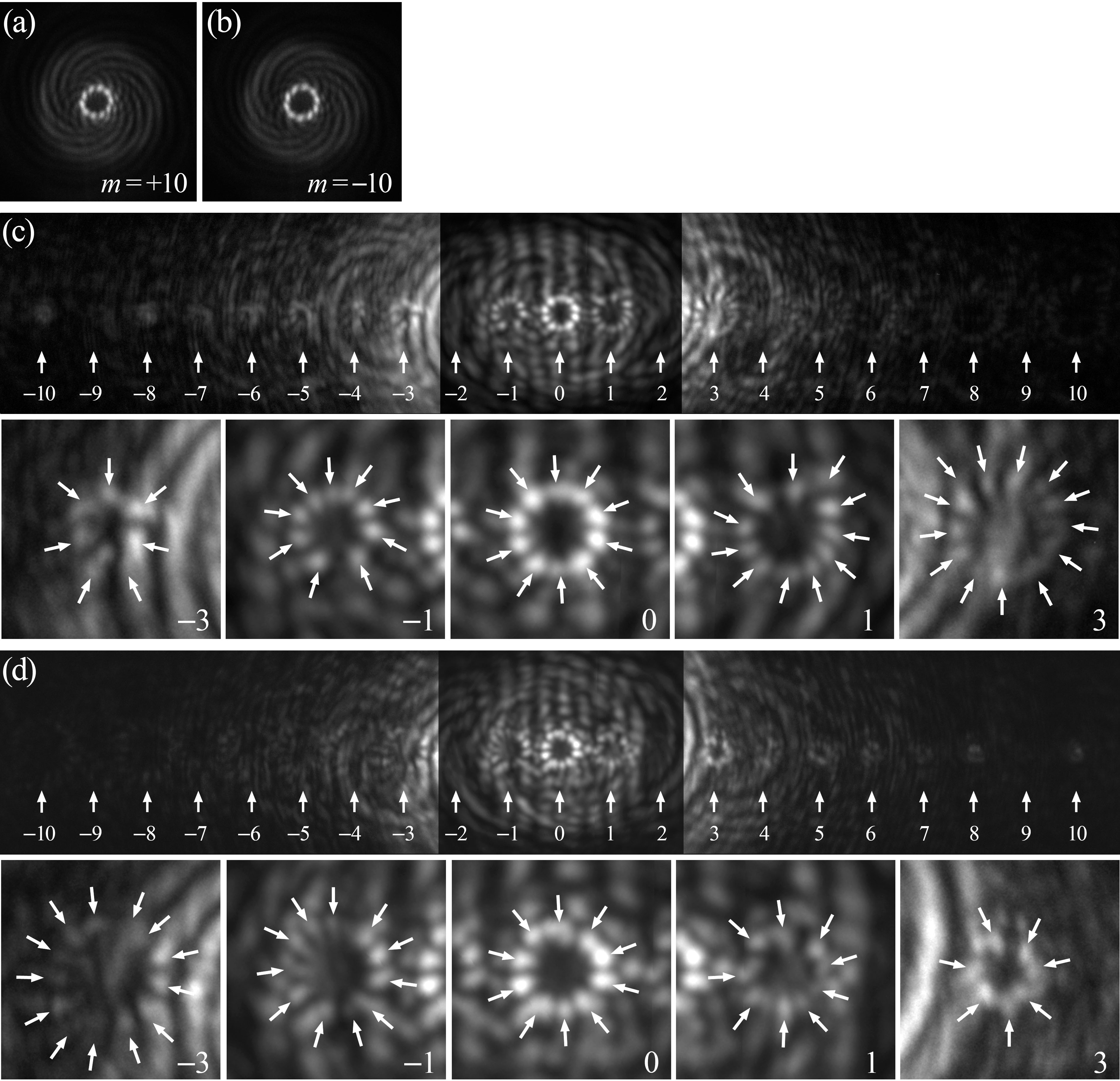
Figures 2(a) and 2(b) show electron vortex beams with OAMs of 10h and -10h, respectively, produced by the spiral zone plate. Each of the electron beams show a ring composed of 10 peaks at the center [4]. Figure 2(c) shows an electron diffraction pattern for an incident electron vortex beam with m = 10h. The diffraction pattern shows a series of diffracted rings, as indicated by the arrows. The central ring, composed of 10 peaks, is the transmitted beam with m = 10h. The 1st- and -1st-order diffracted electron beams show similar ringlike features, but have 11 and 9 peaks, respectively. This indicates that the electron OAMs of the 1st- and -1st-order diffracted beams are 11h and 9h, respectively. Figure 2(d) shows an electron diffraction pattern for an incident electron vortex beam with m = -10h. The pattern shows a series of diffracted rings as in Fig. 2(c), but is horizontally inverted from that shown in Fig. 2(c). The transmitted (0th-), 1st-, and -1st-order diffracted rings show 10, 9, and 11 peaks, respectively, indicating that the electron OAM of the 1st- and -1st-order beams are -9h and -11h, respectively. Our results indicate that the forked grating with a Burgers vector of b = 1 transfers not only linear momentum but also OAM, where the electron OAM transfer of the nth-order diffracted electron beam is nh. This diffraction property could be used as an electron OAM analyzer, as the nth-order diffracted beam shows a normal peak.
References
[1] M. Uchida and A. Tonomura, Nature 464, 737 (2010).
[2] J. Verbeeck, H. Tian, and P. Schattschneider, Nature 467, 301 (2010).
[3] K. Saitoh et al, Phys. Rev. Lett. 111, 074801 (2013).
[4] K. Saitoh et al., J. Electron Microsc. 61, 171 (2012).
The present work was partly supported by the Grant-in-Aid for Scientific Research (A) (No. 23241036), the Ministry of Education, Culture, Sports, Science and Technology, Japan, and the Mitsubishi Foundation.

