IT-7-P-2970 Light Irradiation of ETEM Samples for In-Situ Studies of Photocatalysts
Inorganic photocatalysts are currently being intensely studied for their potential use for the production of fuels from H2O and CO2. Designing new efficient photocatalysts requires an increased understanding of the link between catalyst microstructure and activity. Environmental TEM (ETEM) is a promising technique for elucidating this link. However, while gaseous environments and variable temperatures are common to ETEM work, illumination of the sample by visible, ultraviolet, and infrared light is much less common.
We have installed a variable wavelength light source to irradiate the sample area in an FEI Tecnai F20 ETEM [1]. This will allow detailed analysis of the interaction between light and photocatalysts under reaction conditions. The current design, as seen in Figure 1, consists of a broadband light source with filters, optical fibers with a vacuum feedthrough, and a manipulator to precisely position the fiber tip with respect to the TEM sample in the microscope. The Energetiq® light source we use is a xenon lamp which is powered by an infrared laser, rather than the standard arc discharge, providing a smaller and brighter source. As seen in Figure 2, the broadband light source is capable of illuminating the sample with high intensity over a broad range of wavelengths. Optical filters may be used to specify smaller pass-bands. The measured intensity distribution at the sample position is sharply peaked at the center, reaching a maximum of about 1400 mW/cm2. This is more intense than the typical solar irradiance on the Earth’s surface which is only about 100 mW/cm2. The area of the sample illuminated with at least 90% of the peak intensity is an ellipse about 200x400 μm in size. This is large enough to cover 8 grid squares in a 200 mesh TEM grid. As shown in Figure 3, the fiber comes into the TEM at 90° to the sample rod, and the tip is cut at an angle, which refracts the light up toward the TEM sample. The angle chosen for this design was 30°, in order to sufficiently refract the light exiting the fiber while avoiding total internal reflection at the tip. This configuration, with the fiber independent of the sample rod, gives flexibility in the choice of sample holders, allowing other in-situ capabilities simultaneous to the light illumination. We are using this new capability to study the structure of titania-based nanostructured photocatalysts, and have observed changes in the surface of the titania when exposed to water and UV irradiation [2].
References:
[1] Miller, B. K.. and Crozier, P. A. Microscopy and Microanalysis 19, 461-469. (2013).
[2] Zhang, L. and Crozier, P. A. Nano Letters 13, 679-684. (2013).
The support from US Department of Energy (DE-SC0004954) and the use of ETEM at John M. Cowley Center for High Resolution Microscopy at Arizona State University is gratefully acknowledged.
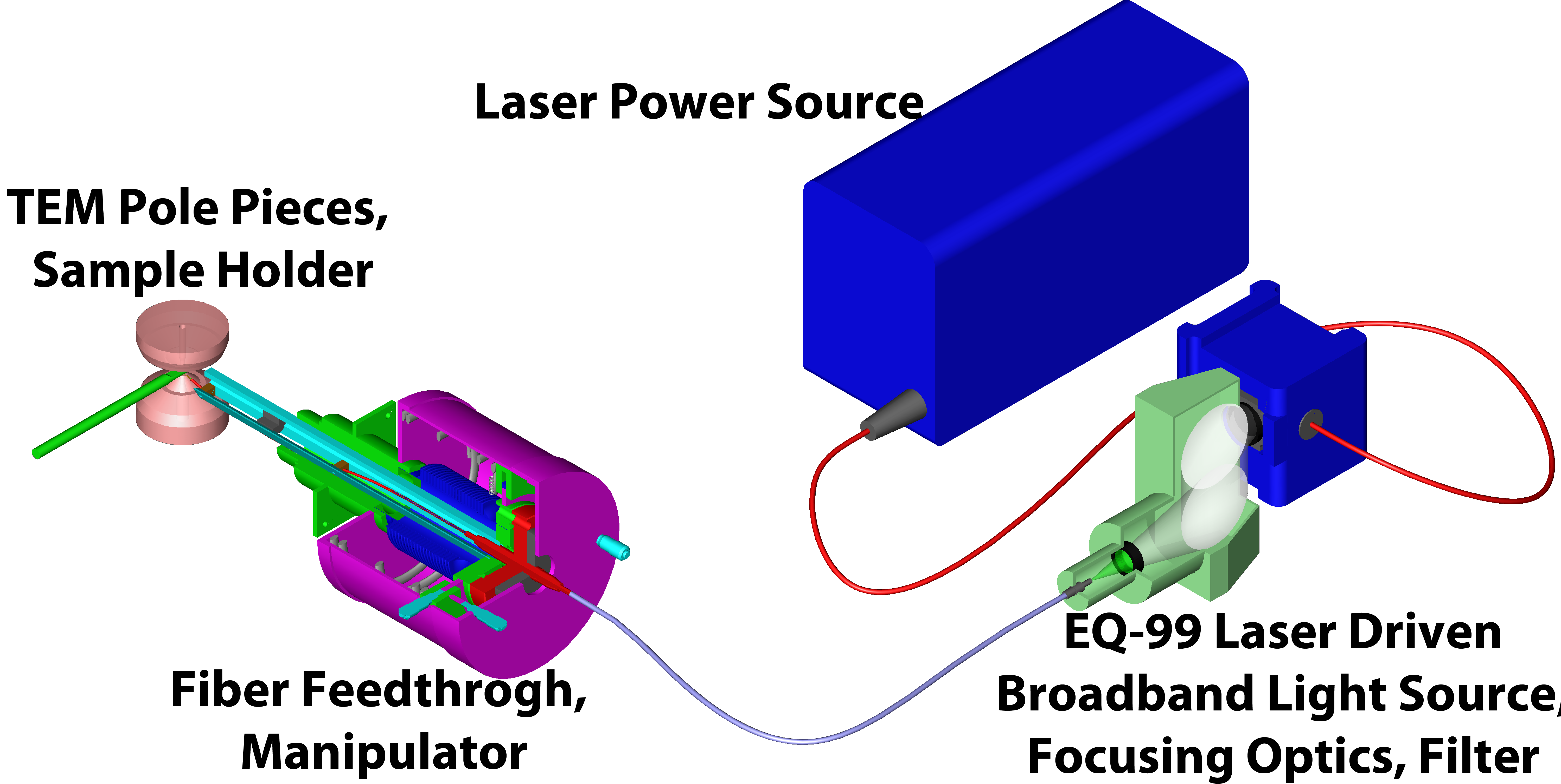
Fig. 1: Overview of the light illumination system, showing the laser driven broadband light source, optics, and fiber manipulator. The monochromatic laser is used to power a xenon plasma which produces the broadband light. |
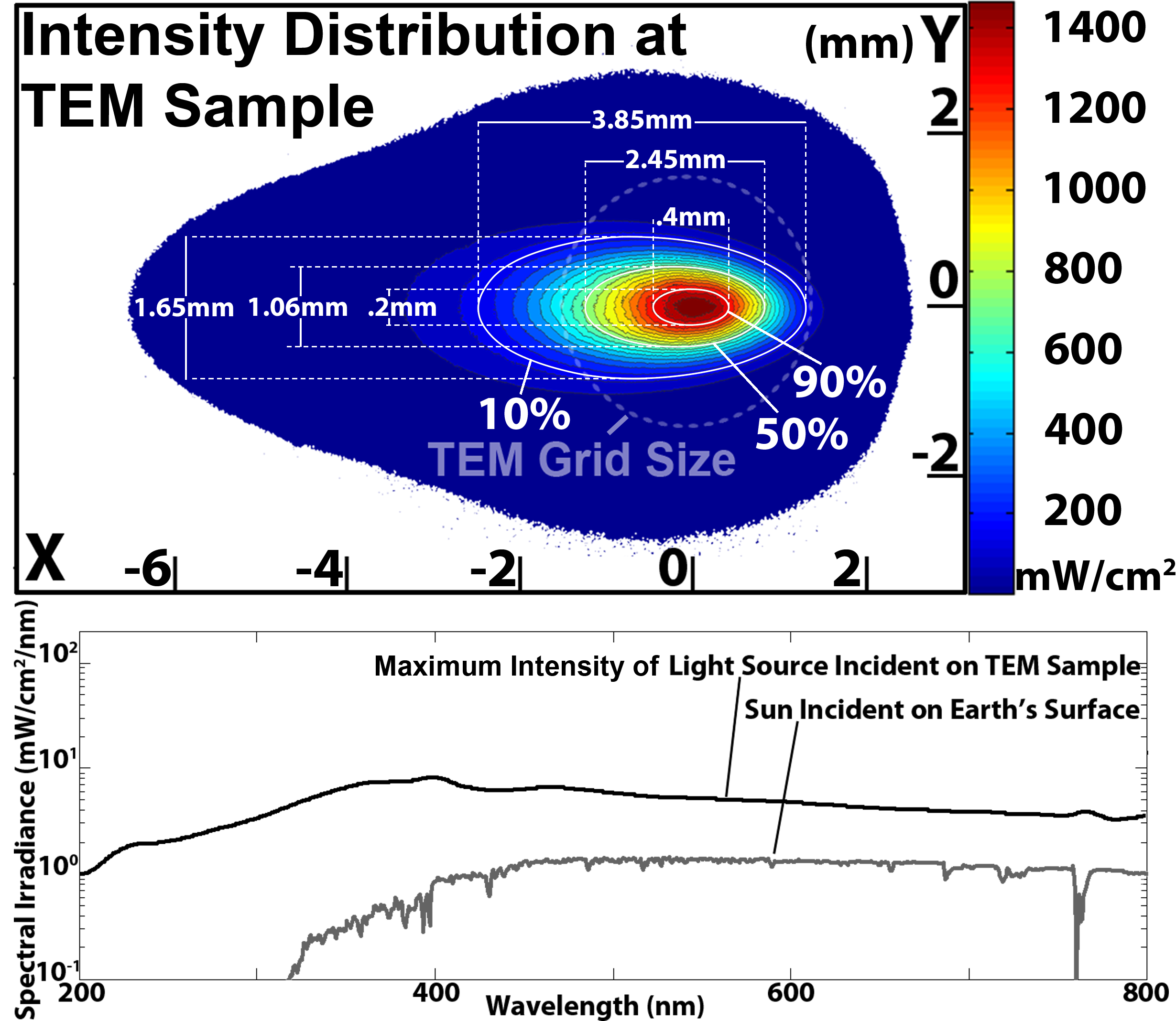
Fig. 2: Light characterization, both spatial and spectral. The spatial distribution shows the intensity variation at the sample position. A faint dashed circle indicates the size of a 3mm TEM sample. The spectral distribution of the light is compared to the solar spectrum incident on the Earth’s surface. |
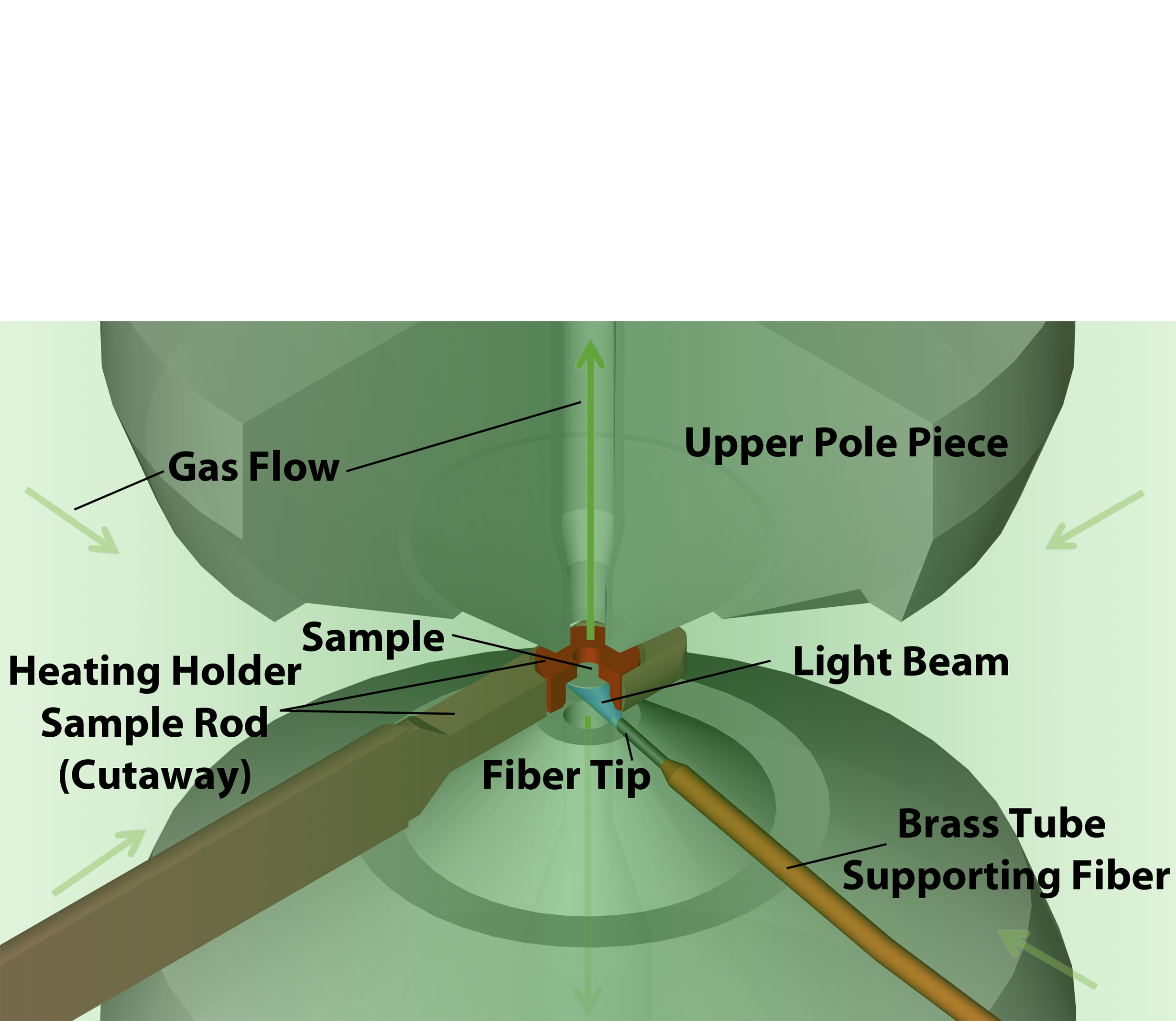
Fig. 3: Cutaway view of the fiber as it extends into the pole piece gap. The fiber is supported at a 90° angle to the sample rod. The fiber tip is positioned close enough to the sample to provide maximum intensity without interfering with sample tilt. The tip is cut at an angle to refract light up toward the sample. |
|