IT-9-O-2773 Combining real space and reciprocal space tomography in the TEM
Precession electron diffraction (PED) [1] is a valuable technique for investigating crystal structures and when combined with a well-defined raster is able to produce high quality virtual dark-field (VDF) images and orientation maps [2] with ca. nm resolution. Many microstructures vary in all 3 dimensions and tomographic techniques are needed to investigate such complex structures. Combining scanning PED (SPED) with electron tomography offers a way to study local orientation across a volume of interest in 3D.
In this study a tilt-series (from -60o to +70o with 5o steps) of SPED images were recorded from a Ni-base superalloy sample, the scanned maps were recorded with 140x140px of 7.5nm step with a 5nm probe and a precession angle was 0.5o. The image processing is shown in Fig. 1: a) a VDF image (at 5o) that shows a large (ca. 200nm) precipitate, b) shows a VDF image of a smaller (ca. 50nm) inclusion, c) shows the components in the microstructure after segmentation. Geometric tomography (shape-from-silhouette) [3] was used to recombine the VDF tilt-series into a tomogram, Fig. 1(d). The tomogram allowed the contributions to each diffraction pattern in the tilt-series to be determined. As such, the individual diffraction components could be isolated and combined to produce 3D reciprocal lattice reconstructions.
The smaller particle was found to have the ordered η-phase structure (sp. gr. P63/mmc, a=5.314Å and c=8.351Å), the larger precipitate had the MC carbide structure (sp. gr. Fm3m, a=4.32Å) and the γ-matrix has the disordered fcc structure (sp. gr. Fm3m, a=3.59Å). The correspondence between the orientation of the diffraction pattern and the tilt step allowed the orientation of the different phases to be examined. The (001) plane of η-phase has a coherent registry with (111) of the γ-matrix. A test of the reciprocal lattice alignment confirmed that this registry existed across the ‘top’ facet of the inclusion. In the literature there has been no reported registry between the MC and γ phases. However, the front facet of the precipitate (shown in Fig. 2a) was found to be parallel to the (111) plane, the projected reciprocal lattice from this component at the appropriate orientation is shown in Fig. 2(b). The corresponding reciprocal lattice for the matrix is shown in Fig. 2(c) and returned the (531) plane as the matrix surface. Since the entire reciprocal lattice is projected, for clarity the ZOLZ reflections are highlighted and indexed where appropriate. Analysis of the interface showed a semi-coherent registry with the inclusion of a small interface strain (ca. 4%).
[1] R. Vincent & P. A. Midgley, Ultram. 53 (1994), 271-282
[2] P. Moeck et al. Cryst. Res. Tech., 46 (2011), 589-606
[3] Z. Saghi et al. J. Phys. Conf. Ser. 126 (2008) 012063
The authors acknowledge funding from the ERC though grant 291522-3DIMAGE, the 7th Framework Programme of the EC: ESTEEM2 and Rolls Royce plc.
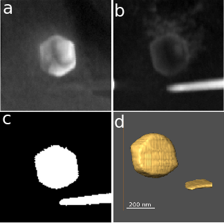
Fig. 1: Figure 1a) and b) virtual dark-field images of second phase particles in a nickel-base superalloy microstructure, c) segmented image of the two particles and d) representative surface render of the reconstructed tomogram. |
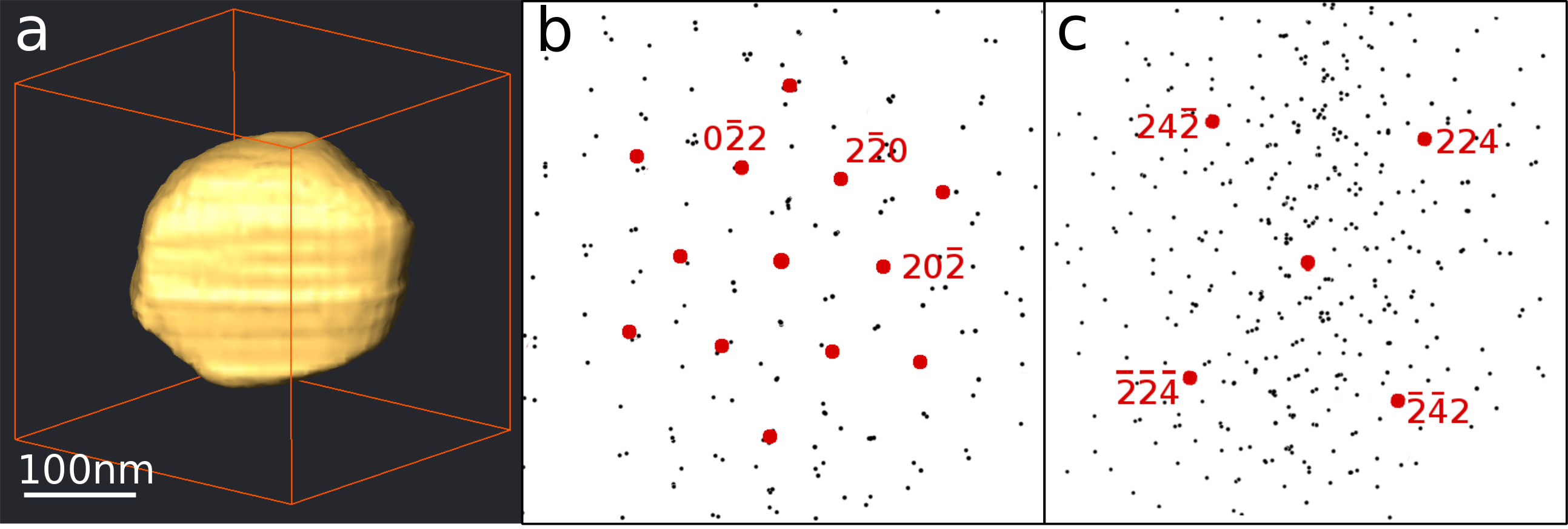
Fig. 2: Figure 2a) Tomogram surface of a carbide precipitate normal to its largest facet. b) and c) projections of the reconstructed reciprocal lattices from the carbide and matrix, respectively, at the same orientation. The ZOLZ reflections are highlighted in each showing that the interface is composed of tye carbide (111) and the matrix (531) planes |