IT-8-P-2668 Ultrafast measurement in spin- polarized pulse TEM
Investigations of ultra-high-speed phenomena in nanometer scale are important for analysis of dynamics in advanced nano-devices. Furthermore, measurement of a spin information is necessary for densification of magnetic recordings and developments of spintronics devices. It is expected that spin-polarized transmission electron microscopy (SP-TEM) can clarify the spin-dependent dynamics.
The SP-TEM consists of a laser-driven electron source and a conventional TEM (Hitachi H9000-UHV). The electron source is configured with GaAs-GaAsP strained superlattice photocathode using a negative electron affinity surface, which has high polarization of 92% and high quantum efficiency of 0.5% [1]. Moreover, the photocathode also has an ability of generating a sub-picosecond pulsed electron beam [2]. The Pulsed electron beam is emitted by illuminating a pulse laser to the photocathode.
Figure.1 (a) and (b) show the TEM images obtained by using a continual electron beam and pulsed electron beam, respectively. The image of Fig.1 (a) is wobbled TEM image by an alignment deflector coil. The wobbling amplitude is dramatically decreased by using the pulse beam as shown in Fig.1 (b) [3]. Fig.2 is an illustration of an optical bench for a pump-probe method. A femtosecond pulse laser is separated two beam line by a polarized beam splitter. One of the beam line is delayed by passing a variable delay-line. The other is irradiated to a dispersive grating as a pulsewidth stretcher and extracts sub-picosecond pulse laser. Each of lasers are transferred to the SP-TEM by using optical fibers. Fig.3 shows the pulse-duration of a picosecond pulse laser measured by an auto-correlator. The picosecond pulse lasers are generated by selecting a part of the wavelength of femtosecond pulse laser.
Consequently, a pump-probe method which picosecond and femtosecond pulse lasers are used for photocathode and specimen excitation respectively can be carried out in the SP-TEM. This instrument gives a possibility of investigations of spin dependent phenomena with a high temporal resolution such as a time-evolution of photo-induced magnetism on nanometer scale.
[1] X G Jin et al., Appl. Phys. Express 1. (2008) 045002
[2] Y. Honda et al., Jpn. J. Appl. Phys. 52 (2013) 086401.
[3] M. Kuwahara et al., Microscopy 62 (6) (2013) 607-614.
The authors thank Drs. H. Shinada, M. Koguchi and M. Tomita of Hitachi Central Research Laboratory for fruitful discussions and encouragement. This research was supported by MEXT KAKENHI Grant Number 51996964, 24651123, 25706031 and Kurata Research Grants from the Kurata Foundation.
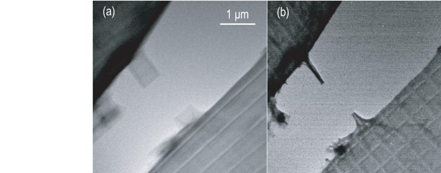
Fig. 1: Wobbling TEM images acquired by illuminating (a) continual electron beam and (b) pulsed beam. |
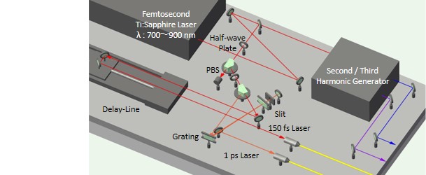
Fig. 2: A schematic of the optical bench for the pulse laser. |
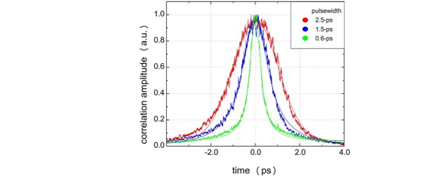
Fig. 3: Correlation time-structures of series of picosecond pulse lasers measured by an auto-correlator. |
|