IT-13-P-2616 In situ FIB/SEM micro-compression tests of layered crystals
Keywords: micro-compression, layered crystals, FIB, transition metal dichalcogenides
With the recent surge of interest in two-dimensional materials other than graphene, transition metal dichalcogenides (TMDCs) have gained a lot of attention because of their outstanding properties ranging from superconductivity to the formation of charge density waves [1, 2]. However not only monolayers of TMDCs are of interest, since the bulk form also shows strongly anisotropic behavior in most physical properties, which makes TMDCs promising candidates for many applications such as solid lubrication [3]. The anisotropic behavior in these layered crystals arises from the contrast between the weak Van der Waals bonding between the layers and the strong ionic/covalent bonds within the layers. Despite the amount of attention that this class of material has gained, the mechanical properties are largely unknown. This is due to the difficulty of preparing samples that are suitable for traditional mechanical testing. Consequently compression tests of micro-pillars are emerging as a novel way to measure the mechanical properties of materials on a micro scale [4].
In this contribution we show the preparation of micro-pillar samples from layered crystals, choosing vanadium diselenide (VSe2) as model material system. An FEI Helios Nanolab 660 DualBeam has been equipped for both sample preparation and in situ compression of the studied pillars. The pillars have been prepared using the focused ion beam (FIB), compression has been performed using a Kleindiek micromanipulator while imaging in situ using SEM. Force measurement is enabled using a Kleindiek SpringTable. Image correlation is used to determine the deflection of a cantilever, which corresponds to a force via a known spring constant. Deformation is measured tracking the difference in displacements between substrate and pillar. The complete indentation setup is shown in Figure 1.
Figure 2 shows the compression of an exemplary VSe2 pillar, cut at an angle of 20 degrees from the basal planes. The inset shows the resulting force displacement diagram. As expected a preferential slip along the basal planes is clearly visible. The sample preparation and micro-compression testing route established in this work on the example of VSe2 is anticipated to provide a deeper insight on the mechanical properties of TMDCs and other more complex layered crystals , like, e.g., misfit layer compounds.
References
[1] Q H Wang et. al., Nat. Nanotechnol., 2012, 7, 699–712
[2] X Huang et. al., Chem. Soc. Rev., 2013, 42, 1934
[3] L Rapoport et. al., J. Mater. Chem., 2005, 15, 1782–1788
[4] M D Uchic et. al., Science, 2004, 305, 986
The Authors gratefully acknowledge financial support by the German Research Foundation (DFG) via the research training group 1896 „In situ microscopy with electrons, X-rays and scanning probes”.
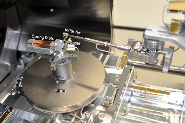
Fig. 1: The Kleindiek indenter setup inside the chamber of the focused ion beam. |
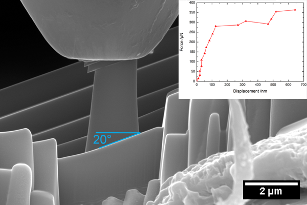
Fig. 2: SEM-image of a vanadium diselenide pillar (prepared at an angle of 20° relative to the basal planes) being compressed by a diamond flat punch and the resulting force displacement curve (inset). |