IT-1-IN-2597 Electron Optics for High-brightness High-beam-current Column Design --- extracting micro-amperes from point cathodes ---
A principal goal of designing electron probe forming system is to focus desired beam current into as small a spot on the target as possible. Increasing demand for analytical measurements is making desired beam current higher than ever (Ib>10nA). This article describes strategies to design high-brightness high-beam-current electron optical columns.
Figure 1 shows Probe Property that relates the beam current Ib to the probe size d. The dotted curve assumes as electron source a thermionic gun while the dashed curve is for conventional ZrO/W (100) Schottky emitter (SE) gun system. A higher brightness of the latter makes the probe size substantially smaller in the middle beam current regime. However, the probe blurs fast once the current exceeds a certain threshold.
Probe Property is limited by three different mechanisms with increasing beam current order:
Beam Current Regime “low” “middle” “high”
Limiting Mechanisms wavelength brightness angular intensity
chromatic(OL) spherical(OL) spherical(Gun)
Attempts were made to improve “high” beam current performance by increasing the source angular intensity and suppressing the gun spherical aberration. Extended Paraxial Trajectory Method is used to analyze electron rays starting from cathode surface with large slopes [1]. The emission characteristic of SE gun is then given by optical parameters familiar in lens designs.
The first strategy is to adopt an emitter whose tip radius is significantly larger [2]. Figure 2 compares a scaled-up emitter (giant SE = GSE) with a conventional SE. The tip size effect is reflected in “electron gun focal length,” f. The angular intensity is given by JΩ = f2*js where js is the cathode current density. Since the focal length is roughly proportional to the tip size, a large tip leads to an improved angular intensity.
The second strategy is to immerse the emitter in the condenser lens field, which is known to result in a suppressed spherical aberration.
Figure 3 compares the source emittance diagrams of conventional SE and GSE. GSE’s wide and less-distorted diagram demonstrates its high-beam-current capability. It is expected GSE’s improved emittance extends the “middle” beam current regime to Ib ~ 1μA (see Fig.1).
A test column was constructed by combining the GSE gun with an objective lens designed for efficient X-ray detection. SEM image observations at Vacc = 10kV over beam current range 100pA <Ib< 3μA confirmed semi-quantitatively the predicted probe property given in Fig.1.
[1] S.Fujita, M.Takebe, W.Ushio and H.Shimoyama, J.Electron Microsc. 59, 3 (2010).
[2] S.Fujita, T.R.C.Wells, W.Ushio, H.Sato, and M.M.El-Gomati, J.Microsc. 239, 215 (2010).
The authors thank Shimadzu Corporation for the support of this work as well as for the permission of the publication.
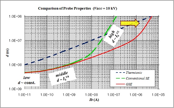
Fig. 1: Probe Properties with three different electron sources. Expected probe size is plotted against the beam current. |
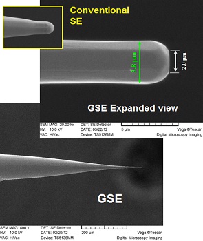
Fig. 2: Comparison of tip geometries of conventional SE and scaled-up emitter (GSE). Angular intensity can be increased by a larger tip radius. |
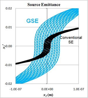
Fig. 3: Source emittance diagrams of conventional SE and GSE. GSE’s wide and less-distorted emittance demonstrates an improved high-beam-current capability of the emitter. |
|