IT-1-P-2469 Electron differential phase microscopy with an A-B effect phase plate
Observations of week phase objects, such as thin films of light elements, thin polymer films, biological sections etc., are available by electron phase microscopy[1]. Many of phase plates utilized are thin film types. Some electrostatic types have been developed, but they are not so general, because the fabrication of the filter with fine structures is very difficult. The mainstream of todays phase plate is the thin film type. This type of the phase plate, however, has some disadvantages, i.e. control of the film thickness, charging up, contamination and so on. We adopted the phase plate with a magnetic thin filament which generates the vector potential around itself by an Aharonov-Bohm (A-B) effect. The filament type phase plate with the A-B effect was proposed and constructed firstly by Nagayama. This type of the phase plate generates the differential phase contrast in the image, and has a longer life time than the thin film type. Any clear differential effect, however, has scarcely reported so far.
We will report that the effect of a phase plate consisting of a Wollaston platinum filament of 1 µm in diameter covered with ferromagnetic material, Nd-Fe-B of 5 nm thick, deposited by Pules Laser Deposition. The filament with a clean surface selected by SEM is mounted on a single hole Cu grid. The phase difference in the both side spaces of the filament measured by electron holography shows 1.5 rad as shown in Fig.1. Being set on the aperture holder, the phase plate is inserted in the back focal plane of the objective. Figure 2 shows images of a colon bacillus stained with Pb. Fine structures can be observed clearer in the image using the phase plate than in the image taken ordinarily. The direction of the differentiation is shown by the arrowhead.
Refernce
[1]K. Nagayama, Another 60 years in electron microscopy: development of phase-plate electron microscopy and biological applications, Journal of Electron Microscopy, 60(2011) S43-S62.
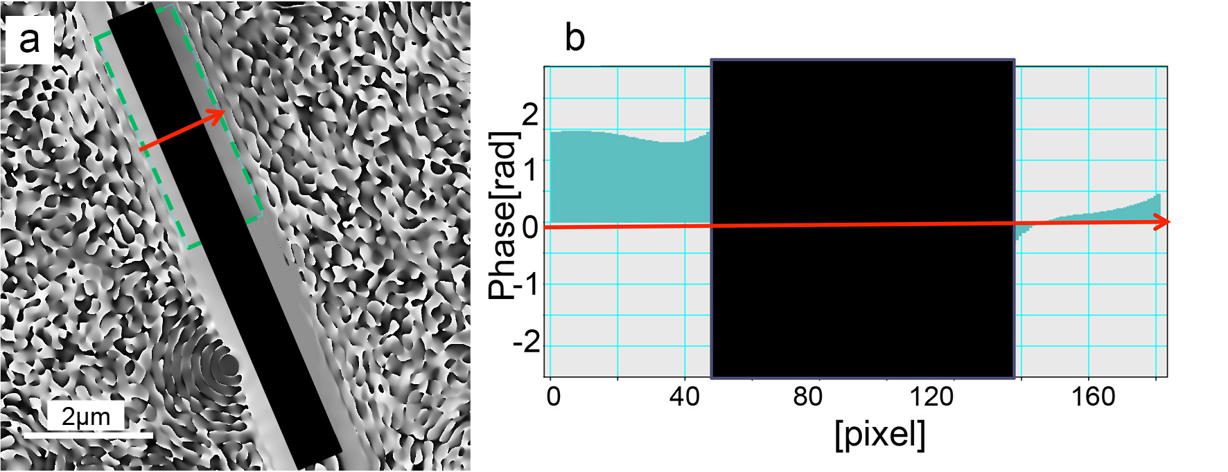
Fig. 1: (a) Electron phase map reconstructed by electron holography. (b) A line profile along the arrow head in (a) which is averaged along the long side of the rectangle. The phase difference is about 1.5 rad. between both sides of the filament. |
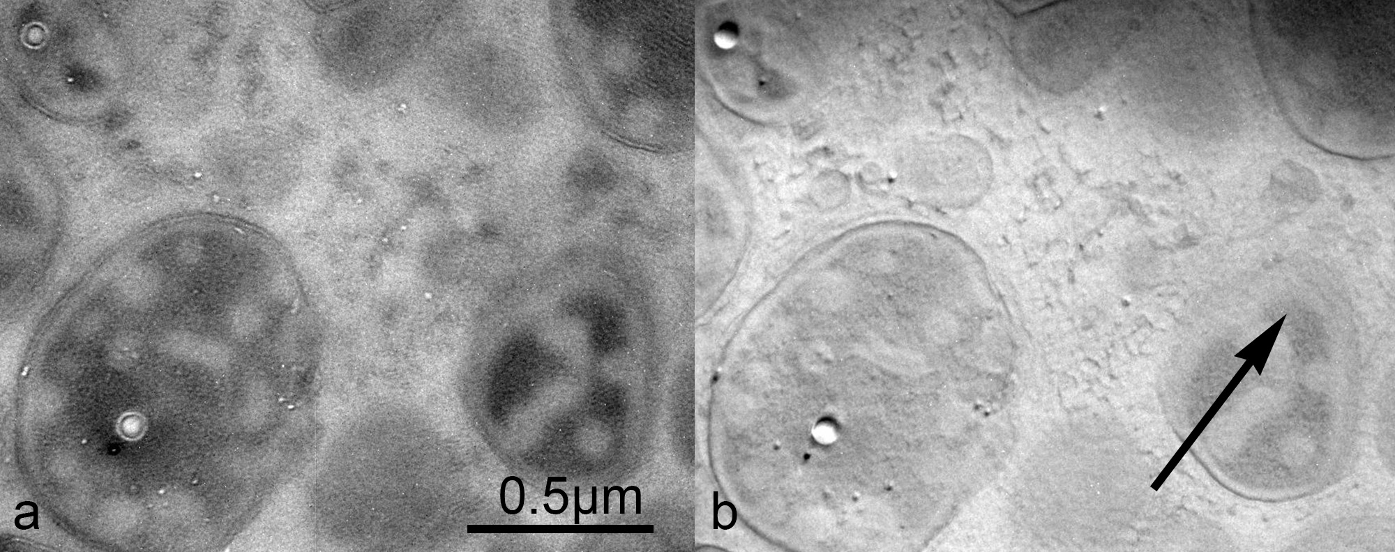
Fig. 2: mages of a colon bacillus stained with Pb taken at under-focus condition without the filament(a) , and in-focus with the filament(b). |