IT-10-O-2435 Towards 4-D EEL spectroscopic scanning confocal electron microscopy (SCEM-EELS) optical sectioning on a Cc and Cs double-corrected transmission electron microscope
The spectrum imaging method of combining scanning transmission electron microscopy with electron energy-loss spectroscopy (STEM-EELS) has been widely used for materials characterization at the atomic-scale. Three dimensional (3-D) optical sectioning using scanning confocal electron microscopy (SCEM) [1], as shown in Fig. 1 a), has been developed as an alternative to tilt-series electron tomography [2]. The confocal imaging mode in STEM has been implemented with spherical aberration (Cs) correctors, which allow the use of substantially increased objective apertures and hence provide a considerably decreased depth of focus, typically below 10 nm. Both the theoretical basis of the image contrast [3] and the experimental implementation of the technique [4-6] have been studied. However, due to Cc-aberrations in the post-specimen optics, inelastically scattered electrons with different energy losses △E are focused at different focal length (Fig. 1a)), which causes an EEL spectrum to be out-of-focus away from the confocal energy loss [5], as shown in Fig. 2a). In order to avoid this problem, a Cc-corrector is need in addition to a double-aberration corrected TEM, as shown in Fig. 1b).
In this work, we propose a novel spectrum imaging mode by combining the SCEM and EELS techniques, which can potentially let one perform 4D EEL spectroscopic SCEM (or so called SCEM-EELS for short) optical sectioning, allowing quantitative chemical characterization over a full 3D specimen volume. Preliminary experiments have been carried out both on a non Cc-corrected Oxford-JEOL 2200MCO instrument with 3rd order double Cs correctors and on a Cc-corrected FEI Titan 60-300 PICO, which has an illumination-side Cs corrector, a Cs-Cc achro-aplanat image corrector and a post-specimen EEL spectrometer. Fig. 2b) shows 2D spectrum images recorded from an amorphous carbon film on the EELS CCD camera in a confocal configuration aligned for energy losses of 0 eV on a Cc-corrected TEM. It demonstrates that the inelastically scattered electrons are simultaneously in-focus on the EELS CCD camera over the entire energy loss range.
References:
[1] P.D. Nellist, P. Wang, Annual Review of Materials Research, 42, (2012), 125-143.
[2] P.A. Midgley, M. Weyland, Ultramicroscopy, 96 (2003) 413-431.
[3] A.J. D'Alfonso et al, Ultramicroscopy, 108 (2008) 1567-1578.
[4] P. Wang et al, Ultramicroscopy, 111 (2011) 877-886.
[5] P. Wang et al, Physical Review Letters, 104 (2010) 200801.
[6] P. Wang et al , Applied Physics Letters, 100 (2012) 213117.
P.W., A.I.K. and P.D.N. acknowledge financial support from the Leverhulme Trust (F/08 749/B), the EPSRC (EP/F048009/1); P.W. acknowledges financial support from the Thousand Talents Program.
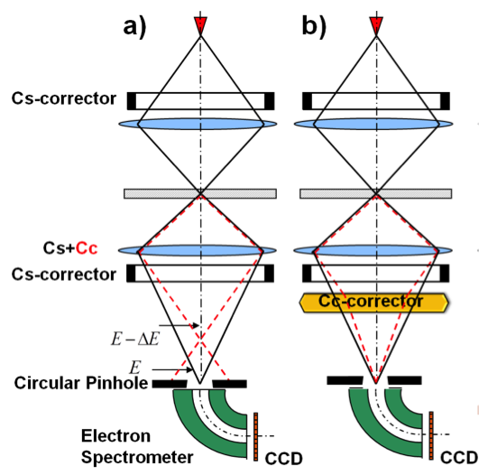
Fig. 1: Schematic diagrams of confocal trajectories for SCEM with an EEL spectrometer behind a circular pinhole on a non Cc-corrected TEM (a) and a Cc-corrected TEM (b), respectively. Due to Cc aberration correction in the post-specimen lenses in (b), electron rays with an energy loss difference of △E can still be focused on the pinhole plane. |
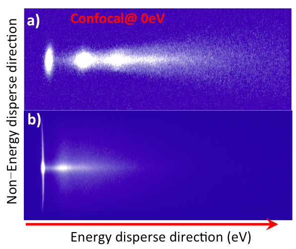
Fig. 2: 2D spectrum images recorded on the EELS CCD camera in a confocal configuration established for energy losses of 0 eV on a non Cc-corrected TEM from a Si slab (a) and on a Cc-corrected TEM from an amorphous carbon film (b), respectively. |