IT-2-P-2307 Observing depth dependent strain via optical sectioning in the STEM
The development of spherical aberration correctors for the scanning transmission electron microscopes (STEM) has led to a reduction in the depth of field, which can be of just a few nanometers in a modern instrument. Since this value is smaller than the typical sample thickness, it creates an opportunity to optically section the sample simply by imaging with the focal plane set to a specific depth within the sample [1]. By recording a series of images over a range of focus values, a full three-dimensional image can be obtained. Here we demonstrate that optical sectioning in the high angle annular dark field mode (HAADF)-STEM mode has a sufficiently small depth of field to detect depth-dependent atomic displacements associated with dislocations in GaN, in particular the so-called Eshelby twist [2]. The Eshelby twist is a consequence of the relaxation of the stresses on the free surfaces of the thin TEM sample in dislocations with a screw component of the Burgers vector normal to the foil. It can be seen as an apparent rotation of the lattice in one surface, with displacements that decrease with increasing depth below the surface until the mid-plane of the foil is reached where no displacements should be observed. A rotation in the opposite sense occurs at the opposite surface.
HAADF images of a GaN crystal containing the displacements associated with a right-handed screw dislocation and the Eshelby twist were simulated at different focus value using SICSTEM [3]. The results indicate that the displacements due to the Eshelby twist become larger as the distance from the core increases within the field of view of the simulations, leading to an apparent overall rotation of the lattice around the dislocation core (Figure 1). This allows the twist to be measured on the lattice planes that are parallel to the fast scan direction in the STEM image, providing an approach very robust to the effects of sample drift and scan distortion.
We show that the Eshelby twist can be experimentally measured, by recording focal series in dislocations with a screw component (either pure screw or mixed) imaged end-on. The rotation of the lattice with respect to the image of the crystal at the entrance, as a function of defocus, was measured using the Radon transform [4] (Figure 2), which allowed us to quantify the rotation rate in the different types of dislocations (Figure 3) and us to determine the sign of the screw component of their Burgers vector.
[1] G. Behan et al., Phil. Trans. R. Soc. A 367, 3825 (2009)
[2] J. D Eshelby and A. N. Stroh, Phil. Mag. Series 7 42, 1401 (1951).
[3] J. Pizarro et al. , Appl. Phys. Lett. 93, 153107 (2008).
[4] S. R. Deans, The Radon Transform and Some of Its Applications, New York: John Wiley & Sons (1983)
We gratefully acknowledge financial support from the EPSRC, the Spanish MINECO and the Junta de Andalucía.
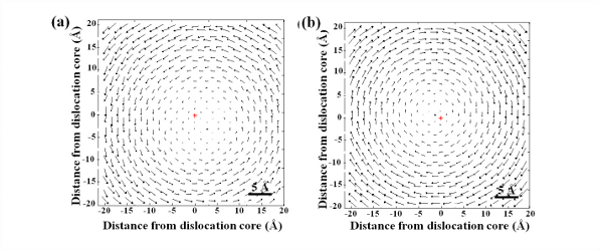
Fig. 1: Displacements maps due to the Eshelby twist for focus values a) 0 nm (entrance surface), b) -10 nm (exit surface) for a GaN crystal with a screw dislocation normal to the foil with the Eshelby twist, and the atomic positions of the infinite crystal. For better visualization, a factor of 10 has been applied. |
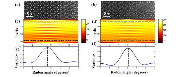
Fig. 2: (a) and (b) show two HR-STEM images of a screw dislocation taken at focus values 4 nm apart, and (c) and (d) their Radon transform maps .(e) and (f) represent the variance of each intensity profile in (c) and (d), where the maximum variance corresponds to the angle at which the horizontal a-planes are aligned with the Radon projection. |
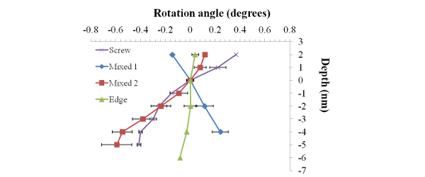
Fig. 3: Experimentally measured rotation angle as a function of defocus for three types of dislocations: a pure screw, a pure edge and two neighbouring mixed dislocations. The rotation is clockwise for the screw and one of the mixed dislocations and anticlockwise for the other. No significant rotation is observed for the pure edge dislocation. |
|