IT-9-O-2147 Using electron vortex beams to distinguish enantiomorphic space groups
Twenty two truly chiral space groups exist which are characterized by a screw axis. They can be divided in eleven enantiomorphic pairs of two space groups being each others mirror image. Telling apart crystals belonging to enantiomorphic space groups appears to be a difficult task. A few methods have been developed making use of dynamical scattering in which experimental observations have to be compared with numerical simulations [1-4]. We propose a new method to distinguish enanthiomorphic space groups without the need for simulations, based on the use of electron vortex beams in the kinematical approximation allowing a direct interpretation of the handedness of a crystal.
Ever since their first creation [5,6], electron vortex beams (EVB) have been subject of intensive research [7]. EVB are solutions of the free space Schrödinger equations of the form Ψ(r,φ,z)=exp(imφ)Ψ(r,z). Being eigenfunctions of the orbital angular momentum operator, they carry a well defined orbital angular momentum (OAM) of mħ per electron and a transverse current around the vortex core. In order for the wave function to be continuous, the intensity of the beam has to be zero in the center of the beam resulting in the well known donut shape of the beam, a bright ring with a dark hole in the middle. As can be seen in fig.1, the wave fronts of such a beam have an helical form. Based on a simple model we have derived a relationship between the symmetry of the higher order Laue zones in the diffraction pattern and the OAM of the vortex when scattered kinematically on helically arranged atoms, as is shown schematically in fig.1. For crystals having one heavy atom near a 3-fold screw axis this provides a simple way of measuring the chirality of the space groups without the need for simulations. We verify our conclusions with multislice simulations of the diffraction patterns shown in fig.2 and fig.3 and we discuss the feasibility with experimental results.
[1] Goodman, P. & Johnson, A. W. S. (1977). Acta Cryst. A33, 997–1001.
[2] Goodman, P. & Secomb, T. W. (1977). Acta Cryst. A33, 126–133.
[3] Haruyuki I. et al. (2003), Acta. Cryst. B59, 802-810.
[4] Johnson, A. W. S. (2007), Acta Cryst. B63, 511-520.
[5] Uchida M. & Tonomura A. (2010), Nature 464, 737.
[6] Verbeeck J., Tian H. & Schattschneider P. (2010), Nature 467, 301.
[7] Verbeeck J. et al. (2014), C. R. Phys., http://dx.doi.org/10.1016/j.crhy.2013.09.014".
This research was supported by an FWO PhD fellowship grant (Aspirant Fonds Wetenschappelijk Onderzoek - Vlaanderen). The authors acknowledge support from the EU under the 7h Framework Program (FP7) under a contract for an Integrated Infrastructure Initiative, Ref. No. 312483-ESTEEM2, the European Research Council under the FP7, ERC grant N246791 – COUNTATOMS and ERC Starting Grant 278510 VORTEX.
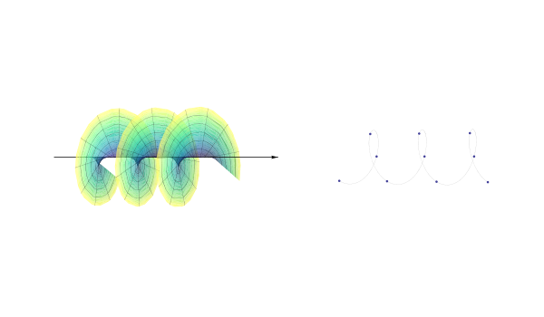
Fig. 1: A vortex beam scattered on helically arranged atoms in a crystal. In our setup the vortex core coincides with the screw-axis and the size with the radius of the helix. |
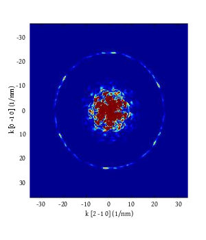
Fig. 2: Multislice simulation of the zeroth and first order Laue zone of the diffraction pattern of a focused 300keV vortex beam with convergence angle 8mRad and OAM=+1, scattered on a 3-fold screw-axis in right handed Mn2Sb2O7. The sample thickness is 20nm. |
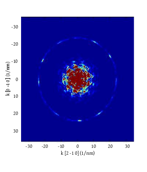
Fig. 3: Same as fig.2 for the left handed enantiomorph. The lack of 2-fold symmetry in the first order Laue zone, in contrast to fig.2, allows a direct interpretation of the handedness of the crystal. |
|