IT-2-P-2042 Contrast Investigation of Annular Bright-Field Imaging in Scanning Transmission Electron Microscopy of LiFePO4
Light elements, such as lithium, are difficult to detect using high-angle annular dark-field imaging (HAADF) in STEM because of their weak atomic scattering. Recently, a novel imaging mode in aberration-corrected STEM was presented which uses an annular detector spanning an angular range mainly within the illumination cone of the focused electron beam1. It was shown that due to the smaller dependence on atomic number Z, approximately Z1/3 compared to Z2 in HAADF, the resultant images enable one to visualize the light element columns2. This imaging mode has been called annular bright-field (ABF) imaging. The contrast differences are clearly visible in Figure 1 which compares HAADF (b) and ABF (c) images of LiFePO4 structure in [010] orientation (a).
In this work, we studied the contrast of ABF imaging in STEM on LiFePO4, correlating results of experiments from the newly installed probe-aberration-corrected JEM-ARM 200CF and simulations using the STEMsim program3. Previous work briefly demonstrated the possibility to acquire direct images of LiFePO4 and partially de-lithiated LiFePO4 at atomic resolution4. Figure 2 presents an experimental comparison of the visualization of lithium in LiFePO4 with HAADF and ABF. The present work aims at presenting a more detailed description of the contrast dynamics of ABF imaging of LiFePO4 with a view to its interpretation, and optimization. Thickness, defocus, angular range, and possible contamination introduced by sample preparation are taken into account to understand the image contrast. In particular, the probe and detector configurations in the microscope are taken into consideration to step from qualitative to quantitative contrast evaluation.
1. Okunishi, E.; Ishikawa, I.; Sawada, H.; Hosokawa, F.; Hori, M.; Kondo, Y., Visualization of Light Elements at Ultrahigh Resolution by STEM Annular Bright Field Microscopy. Microsc Microanal 2009, 15, 164-165.
2. Findlay, S. D.; Shibata, N.; Sawada, H.; Okunishi, E.; Kondo, Y.; Ikuhara, Y., Dynamics of annular bright field imaging in scanning transmission electron microscopy. Ultramicroscopy 2010, 110 (7), 903-923.
3. Rosenauer, A.; Schowalter, M., STEMSIM-a New Software Tool for Simulation of STEM HAADF Z-Contrast Imaging. Springer Proc Phys 2008, 120, 169-172.
4. Gu, L.; Zhu, C. B.; Li, H.; Yu, Y.; Li, C. L.; Tsukimoto, S.; Maier, J.; Ikuhara, Y., Direct Observation of Lithium Staging in Partially Delithiated LiFePO(4) at Atomic Resolution. J Am Chem Soc 2011, 133 (13), 4661-4663.
The research leading to these results has received funding from the European Union Seventh Framework Programme [FP7/2007-2013] under grant agreement n°312483 (ESTEEM2).
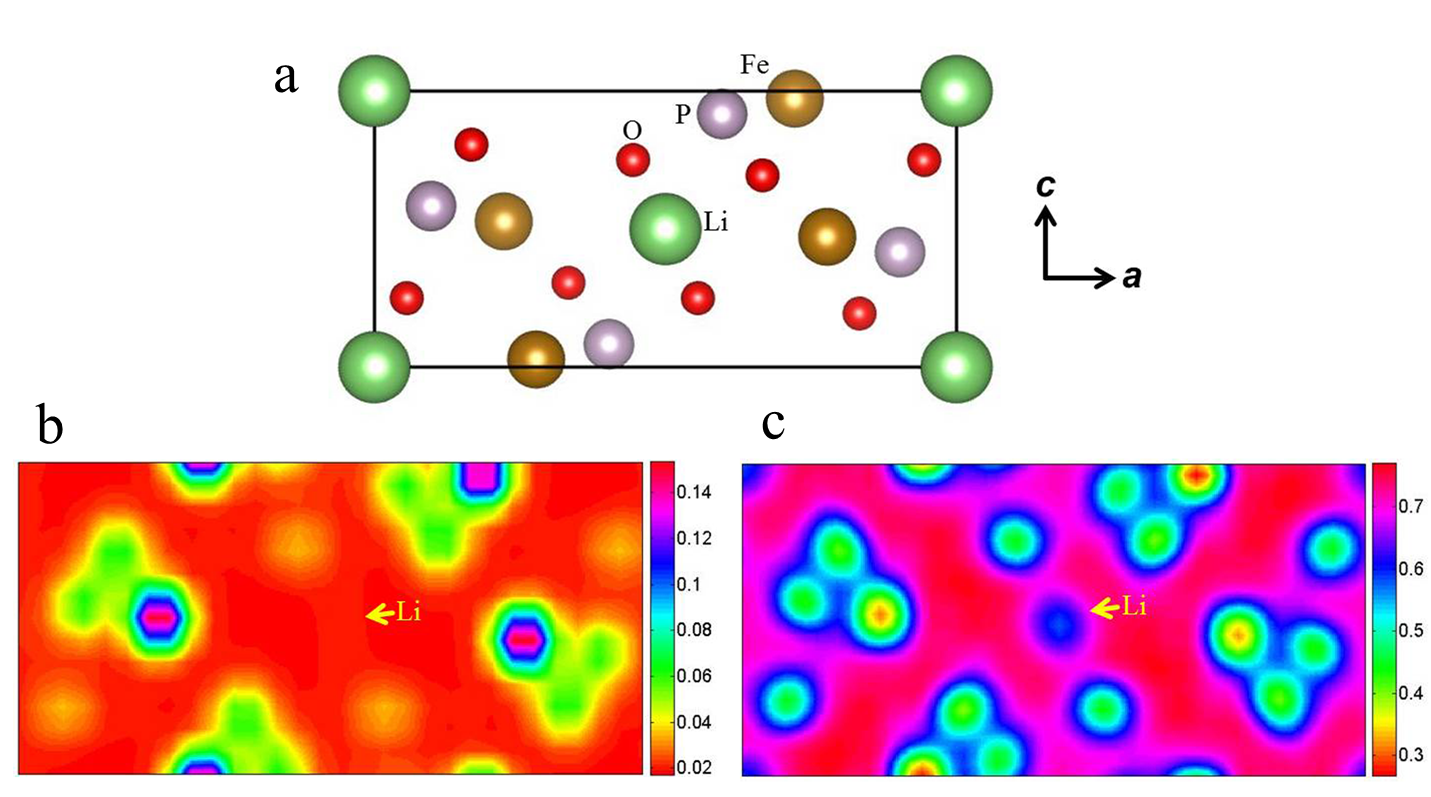
Fig. 1: (a) Projection of the LiFePO4 crystal structure in [010] orientation. Simulated HAADF (b, angular range 40-100 mrad) and ABF (c, angular range 11-22 mrad) imaging using STEMsim. The parameters used for simulations are: high voltage 200 kV, convergence angle 22 mrad, spherical aberration 0 mm, defocus 0 nm, specimen thickness 30 nm. |
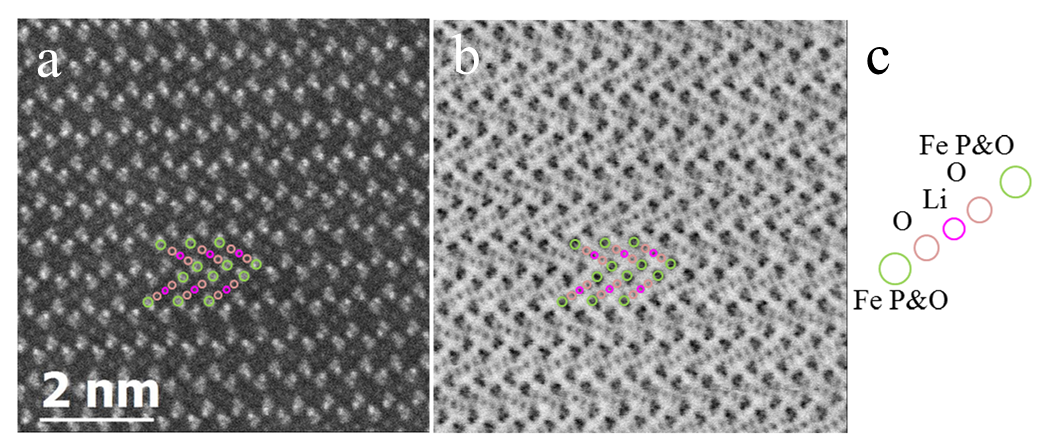
Fig. 2: As acquired experimental results on the visualization of Li in LiFePO4 with HAADF (a, 90-370 mrad) and ABF (b, 11-22 mrad) imaging on the probe-aberration-corrected JEOL JEM-ARM 200CF microscope using a convergence angle of 22 mrad and a probe size of about 0.08 nm. (c) Assignment of atomic column in [010] orientation. |