IT-8-O-2020 Resolving Landau State Dynamics with Electron Vortex Beams
Since the advent of electron vortex beams (EVB) [1] and techniques to routinely produce them in the TEM [2], some exciting applications have been proposed, such as particle manipulation and mapping magnetic moments on the atomic scale, owing to the fact that they carry quantized orbital angular momentum (OAM) of Lz=mħ as well as a quantized magnetic moment of M=µBm per electron. With m being the topological charge m=…,-1,0,+1,….
Recently, it has been argued quantum mechanically [3] and classically [4] that EVB in a homogeneous magnetic field resemble free electron Landau states (LS), exhibiting peculiar azimuthal dynamics that deviate from standard electron optics’ Larmor rotation (Ω), where M=0. Depending on the orientation of M (for M≠0) with respect to the magnetic lens field B, cyclotron (double-Larmor) rotation (2Ω) and no rotation (0Ω) have been predicted. In solid-state physics, these states are well known describing phenomena like the diamagnetism of metals [5]. Even though great advances in mapping LS in solid-state systems have been made, their azimuthal dynamics could not be resolved experimentally so far [6].
The application of EVB opens up the road for the observation of free electron LS in the quasi-homogenous objective lens field in the TEM. In breaking the rotational symmetry of the annular structure of an EVB with a Si-knife-edge, it is possible to resolve azimuthal variations by scanning the EVB along the propagation (z-) direction, see Fig. 1a. Due to the converging character of EVB in the TEM, see Fig. 1b, the free electron LS are only approximated well by the EVB in a specific z-shift region. Fig. 2 shows experimental images from that region. Indeed, m-dependent rotational speeds can be seen. Fig. 3 summarizes the experimental data of many measurements by giving the fitted slopes ‹ω›, which represent the electrons’ rotational speed. There, the comparison to the theoretical calculations indicates excellent agreement with the predicted dynamics of no rotation for m<0 states, Larmor rotation for m=0 and cyclotron rotation for m>0. It conclusively shows the OAM dependent Landau state behavior. Note that with the Larmor frequency being Ω~2π·19GHz, the discrimination between those three rotational states represents an energy resolution of ~100µeV. These findings provide new insight into the fundamental properties of LS and prepare the route towards detailed investigations of their otherwise hidden characteristics.
[1] K Y Bliokh et al, PRL 99 (2007), 190404, M Uchida et al, Nature 464 (2010), 08904
[2] J Verbeeck et al, Nature 467 (2010), 09366
[3] K Y Bliokh, et al, PRX 2 (2012), 014011
[4] T Schachinger, Master Thesis, TU Vienna (2013)
[5] L Landau, Z f Phys 64 (1930) , 629
[6] K Hashimoto et al, PRL 109 (2012), 116805
This work was supported by the Austrian Science Fund FWF (I543-N20) and RIKEN iTHES Project.
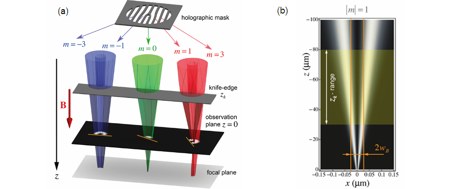
Fig. 1: (a) Sketch of the experimental setup. Half of the incoming beams (blue, green, red), immersed in the B-field of the lens, are blocked by a knife-edge, which is scanned in the z-direction, showing azimuthal dynamics in the observation plane. (b) Cross section of an |m|=1 beam showing the z-region corresponding to the lateral LS extension 2wB. |
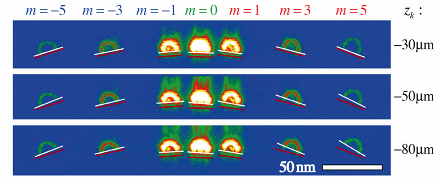
Fig. 2: Experimental images of the cut EVB with azimuthal angle measurements (in false colors), showing m-dependent azimuthal dynamics. Negative m-states show decreased angular variations, while the m=0 and the positive m-states show larger angular variations. The red line acts as a guide to the eye and represents a constant azimuthal angle. |
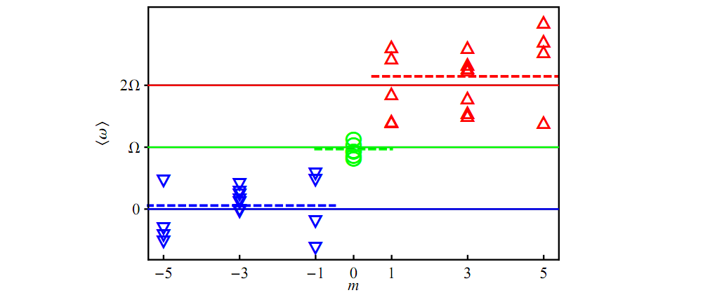
Fig. 3: Scatter plot of the fitted slopes for the LS z-region validating the m-dependent rotational speeds. The solid lines stand for the theoretical slopes, e.g. no rotation (blue), Larmor rotation (green) and cyclotron rotation (red) and the dashed lines represent averaged slopes. |
|