IT-5-O-1900 Calculation and Measurements of XEDS Collection Solid Angle in the AEM
One of the most often misquoted parameters of a solid state x-ray detector interfaced to the AEM is its collection solid angle (Ω). Closed form analytical equations have been developed to calculate the solid angle of six of common geometries of solid-state x-ray detectors[1]. These include cylindrical, rectangular and annular configurations, with the detector in either a tilted or untilted configuration as illustrated in figure 1. These formulae have been integrated into an on-line calculator which is freely accessible and only requires a Javascript compatible browser. It can be accessed at: http://tpm.amc.anl.gov/NJZTools. The use of this tool, removes the ambiguity which besets the community in assessing the relative merits of different manufacturer’s claims, by providing an independent procedure to assess the characteristics of difference detector sizes and their geometries.
Due to the advances in the design and construction of modern Silicon Drift Detectors (SDD) the collection solid angle which in the past has hovered about 0.1-0.15 sR, is now routinely quoted in the 0.2-0.8 sR range. There is is a very little real data published which can be used as a direct measurement of the absolute solid angle or real comparisons of individual system other than anecdotal observations. To illustrate this variation we show measurements of the Ni Kα shell x-ray intensity on 4 different instruments all normalized to the same operating conditions (Figure 2). The performance of a series of 8 analytical electron microscopes, operated at 200 kV were tested independently and their collection solid angle determined. This was accomplished through the measurement of the absolute intensity/nA/nm of the x-ray signal emitted from an amorphous 10 nm thick Germanium specimen[2]. The results of these measurements for the different microscopes, with 18 different detectors configurations are summarized in Figure 3. The largest individual detector tested had a nominal solid angle of ~ 0.24 sR, which agrees well with the calculated value obtain for it using the on-line calculator. For systems with multiple detectors each individual detector was measured, the net solid angle in such situations is the simple sum of from each independent detector value (i.e. instruments 4, 6, 9). The relative variation in the experimental measurements was very large (0.02 sR – 0.24 sR) illustrating the need to quantitatively assess detectors in terms of their real solid angle, rather than the often misinterpreted “Detector Area”.
References
[1] N.J. Zaluzec, Microsc Microanal, 20, in press (2014)
[2] N.J. Zaluzec, Microsc Microanal, 19 (Suppl 2) , 1262-1263, (2013)
doi: 10.1017/S1431927613008301
This work was supported by the U.S. DoE, Office of Basic Energy Sciences, Contract No. DE-AC02-06CH11357 at the Electron Microscopy Center at Argonne National Laboratory.
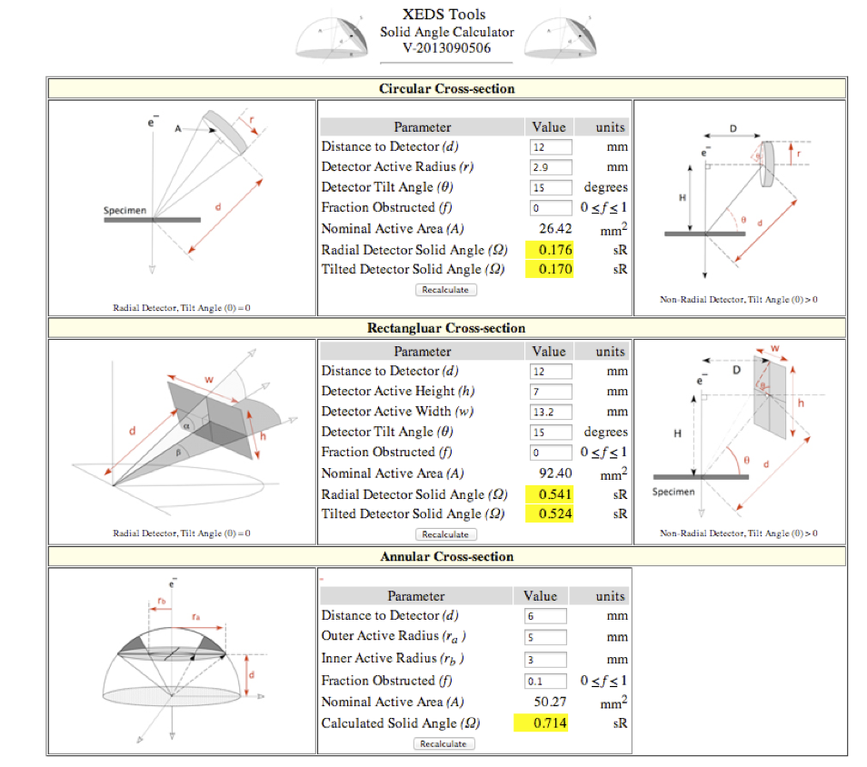
Fig. 1: Figure 1.) User interface to the on-line XEDS Solid Angle Calculator (http://tpm.amc.anl.gov/NJZTools) |
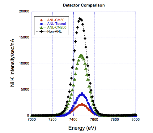
Fig. 2: Figure 2.) Experimental variation of the performance of 4 different 30 mm2 detector systems for the same NiO specimen. |
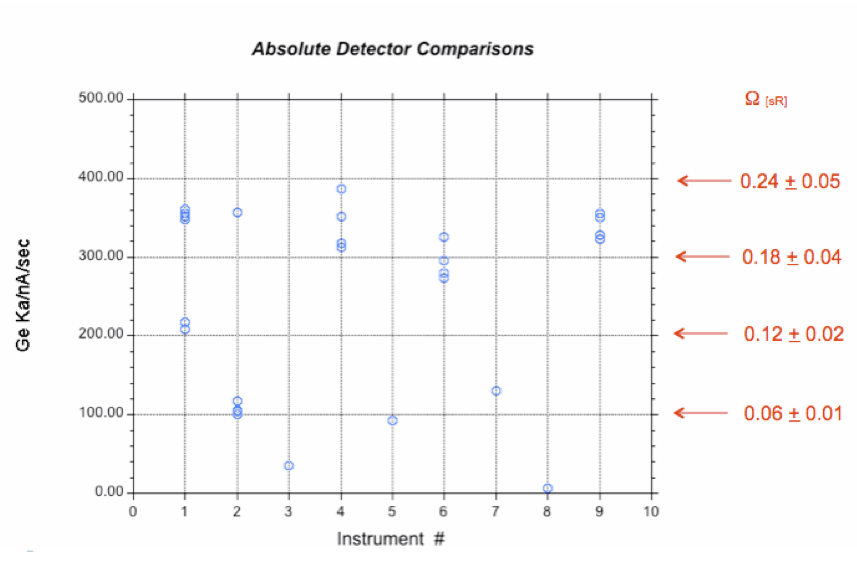
Fig. 3: Figure 3.) Experimental variation of the solid angle as a function of instrument for a 10nm thick amorphous Ge specimen. |
|