IT-2-P-1751 The atomic structure of epitaxially strained LaNiO3-LaGaO3 superlattices
Many functional properties of ABO3 perovskite oxides are closely coupled to slight structural distortions in the perovskite lattice, thus defined symmetry constraints in oxide heterostructures can be used to access novel properties that are not found in bulk constituents [1].
Here, we present our study of an epitaxially strained [4 unit cell (u.c.)//4 u.c] х8 LaNiO3-LaGaO3 (LNO-LGO) superlattice grown on (001) SrTiO3 (STO) substrate (see the model shown in Figure 1). Due to the lattice mismatch, the superlattice is subject to tensile strain. We focus on the determination of the strain-induced distortions (changes in Ni-O bond length) and tilts (changes in Ni-O-Ni bond angle) of the corner-sharing octahedral network, as they may drastically influence the functionalities of the heterostructure. In order to discover the correlation between the NiO6 octahedra rearrangement and the functional properties of the material system, it is essential to study the interfacial structure with atomic-level accuracy. We studied the atomic structure of the octahedral network by means of aberration-corrected high-resolution transmission electron microscopy (AC-HRTEM). In order to enhance the image contrast, negative Cs imaging (NCSI) was applied [2].
Figure 2 is an experimental image of the LNO-LGO superlattice acquired in the vicinity of the top surface in [110] projection. It is clearly seen that the LNO and LGO layers manifest difference in both the zigzagness (out-of-plane corrugation) of BO2 layers and the image contrast. The smooth oscillation of the tilt angles indicates: 1) dissimilarity in tilt systems of each material, 2) proximity effect between adjacent layers. As a result of coherent epitaxial growth, the in-plane lattice parameter d220 remains constant while only the out-of-plane lattice parameter d001 varies. We will discuss further investigation at the substrate-layer interface and answer the question on the assignment of the layers. However, from merely HRTEM imaging, it is difficult to find out which of the layers, LNO or LGO shows the higher out-of-plane corrugation.
[1] H.Y. Hwang, Y. Iwasa, M.Kawasaki, B. Keimer, N.Nagaosa and Y. Tokura, Nat. Mater. 11, 103 (2012).
[2] C. Jia, M. Lentzen and K. Urban, Microsc. Microanal. 10, 174 (2004).
We are grateful to S. Grözinger for assistance with TEM specimen preparation and the German Research Foundation (DFG) for financial support (project DFG: KA 1295/17-1)
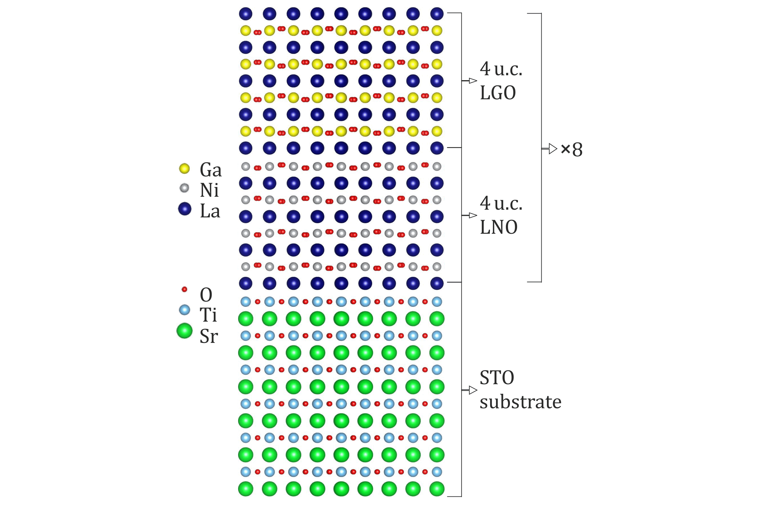
Fig. 1: Atomic structure model of a [4 unit cell (u.c.)//4 u.c] х8 LNO-LGO superlattice grown on STO substrate (viewed in [110] orientation). Unit cells are defined by pseudo-cubic symmetry axes. |
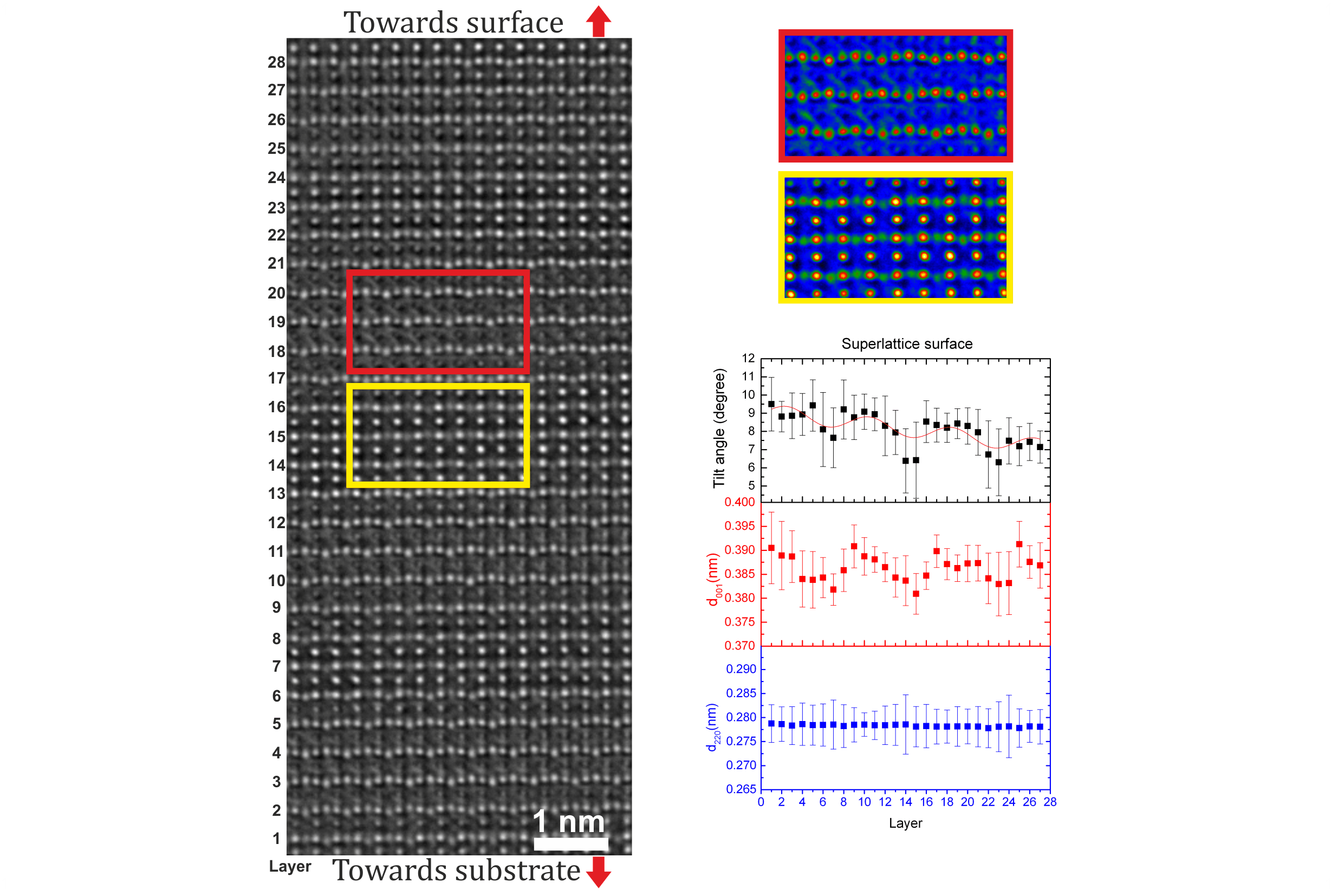
Fig. 2: Experimental aberration corrected image of the LNO-LGO superlattice acquired in [110] projection in the vicinity of the top surface at 300kV. The oscillation of the tilt angles shown in the right diagram indicates non-identical tilt systems in LNO and LGO layers, which is clearly visible from the magnified areas (red and yellow rectangles). |