IT-11-P-1725 Twin-Foucault Imaging for Observing 180° Domains in Magnetic Materials
The conventional Foucault method can visualize magnetic domains under in-focus conditions, but it cannot observe the whole region irradiated by the incident electron beam at once. This is because an off-center objective aperture filters out one of the two deflected beams from materials that have 180° magnetic domains whose magnetizations are in opposite directions to one another. To solve this problem, the twin-Foucault imaging (TFI) method uses an electron biprism instead of an objective aperture to obtain two Foucault images simultaneously [1].
Figure 1(a) shows the optical system for the TFI method using a 300-kV field-emission TEM. The electron biprism was installed between the objective and the first magnifying lenses. When a negative potential is applied to the filament electrode of the biprism, the two electron beams are deflected in dispersive directions away from the optical axis and form two individual Foucault images on the image plane simultaneously. Figure 1(b) shows small angle electron diffraction (SAED) spots from 180° magnetic domains and the shadow of the biprism.
Figure 1(c) shows micrographs of La0.825Sr0.175MnO3 (LSMO) film taken by a CCD camera. The ordinary electron micrograph in the middle panel was divided into two series (upper/lower) of Foucault images with reversed contrast by applying negative/positive potentials to the biprism of ± 50 V and ± 100 V. The winding fringes in the central parts of these images are bend contours, and the vertical black and white stripes in Figs. 1(c) correspond to individual 180° magnetic domains. The Foucault images are switched by the polarity of the applied potential to the biprism.
The TFI method can visualize magnetic domain structures. Figure 1(d) shows examples of processed images of the domain structures. The left panel is an image made by subtracting the right image from the left, i.e., l−r, and the right panel is an image made by subtracting the left from the right, i.e., r−l, in the uppermost panel of Fig. 1(c). In Fig. 1(d), the magnetic domain structures are clearly visible in the reversed contrast in images, whereas the bend contours and other contrasts have been eliminated.
The TFI method can be used to extend the conventional Fresnel method when the applied potential to the biprism is switched off and the specimen is observed in defocused conditions. Figure 1(e) shows over- (left panel) and under-focused (right panel) Fresnel images and in-focus micrograph (center panel).
The TFI method not only has the advantages described here; it can also be used, for example, to observe the dynamics of imaging domain switching. It will lead to new applications in Lorentz microscopy.
References:
[1] Harada, K., Appl. Phys. Lett., 100, 061901 (2012).
The authors would like to thank Prof. S. Mori of Osaka Prefecture University for supplying the LSMO specimens and valuable discussion about the materials.
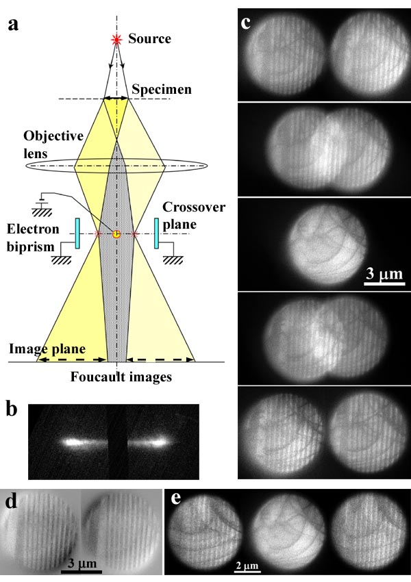
Fig. 1: (a) Optical system for TFI method, (b) SAED pattern with shadow of a filament electrode of a biprism, (c) twin-Foucault images with different potentials from −100 V to 100 V, at intervals of 50 V, (d) 180° domain structures made by subtraction processing of twin-Foucault images, (e) Fresnel images and in-focus micrograph (center panel). |