IT-1-P-1693 Measurement of current density distribution in shaped e-beam writers
The ZrO W(100) Schottky cathode is used in our e-beam writing system working with a rectangular-shaped electron beam. The homogeneous angular current density distribution is crucial for quality of exposures of the shaped beam lithography systems. Two basic types of the angular emission distribution can be observed in dependence on the microscopic final end form shape of the emitter tip, with bright centre and more common dark centre [1]. The stable operation of the cathode thus stable end form shape requires a delicate balance of parameters inside the gun which however can slightly change during cathode life time. This implies the necessity of analysing and periodical monitoring the current density distribution in e-beam. Four methods enabling this measurement are presented.
First we implemented a method based on the modified knife-edge approach [2], when a part of the scanned element of the beam is blanked out and the current within the remaining "open" part is measured. The 2D information of the current distribution is obtained by stepwise opening of selected segments. The measurement error analysis was made and necessary measurement averaging in each segment were used in order to reduce the random error of the current [3]. The size of the scanned element was 6 × 6 µm2, a maximum usable segment for one shot in our lithography system (Fig. 1).
The current distribution obtained by the knife-edge method was compared with a method using a luminescent screen. The YAG:Ce single-crystal screen was irradiated by the e-beam stamp of the 6 × 6 µm2 and the areal light emission was recorded by a magnifying optical system with a CCD camera. The emitted light intensity is directly proportional to the e-beam current, thus the current density distribution can be compared with other measurements methods. However, the absolute measurement is hardly possible (Fig. 2).
Next the same e-beam stamp of the 6 × 6 µm2 was scanned over Faraday cup opening. The advantage of this method is uniform distribution of the measurement error instead of the modified knife-edge method. The absolute value of the current density is affected by the demagnification of the electron optics during measurement (Fig. 3).
Another method is based on evaluation of developed electron resist exposed by the 6 × 6 µm2 separate shaped e-beam stamp using atomic force microscope. The depth of the developed resist depends on the spread of the energy in the electron resist. The real current density distribution was obtained by the deconvolution of the developed resist with electron scattering model (Fig. 4).
References
[1] K-Liu et al., J. Vac. Sci. Technol. B 28, C6C26 (2010).
[2] M. Sakakibara et al., Jpn. J. Appl. Phys. 46, 6616 (2007).
[3] J. Bok et al., J. Vac. Sci. Technol. B 31, 31603-1 (2013).
The authors acknowledge the support from MEYS CR (LO1212) together with EC (ALISI No. CZ.1.05/2.1.00/01.0017), the TACR project No. TE01020118 and institutional support RVO:68081731.
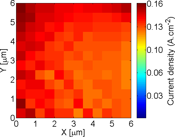
Fig. 1: Modified knife-edge method. |
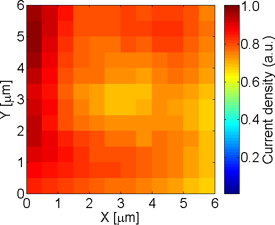
Fig. 2: Luminescent screen method. |
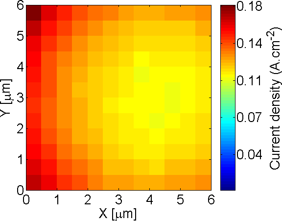
Fig. 3: Faraday cup method. |
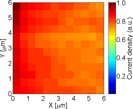
Fig. 4: Electron resist exposure method. |