IT-1-P-1672 Development of illumination system of a 1.2 MV Field Emission Transmission Electron Microscope
In the FIRST Tonomura project, we have been developing a 1.2 MV field-emission transmission electron microscope (FE-TEM) for the atomic resolution three-dimensional reconstruction of electro-magnetic fields by electron holography. Here FIRST stands for funding program for world-leading innovative R&D on science and technology. In this paper we report its illumination system with the following requirements:
(1) high brightness beam for electron holography
(2) current fluctuation less than 10 % over 8 hours for stable observation
The requirement (1) is discussed in this presentation and the requirement (2) is discussed by Kasuya in this conference.
Figure 1 shows schematic view of the illumination system and three ray paths. Separate valves are placed between the FE gun and the accelerator tube so that conditioning of emission and high-voltage can be performed separately. The pre-accelerating magnetic lens focuses the beam near the first electrode of the accelerator tube where the Butler lens is formed (Case A), and then the spherical aberration of the accelerator tube can be suppressed. When the magnetic lens excitation becomes stronger, the electron trajectory focuses twice in the accelerator tube (Case C). Between Case A and Case C, beams focus near the condenser lens and cannot focus on the specimen position (Case B). To obtain high brightness beam, total aberration of the illumination system has to be minimized. The optimum condition of the pre-accelerating magnetic lens was obtained by calculating mean brightness and probe current of the spot focused on the specimen position as a function of the lens excitation using WR5 software (MEBS Ltd.). The FE-cathode source diameter, the angular current density, and the energy spread are assumed to be 5 nm, 30 μA/sr, and 0.3 eV, respectively. Figure 2 shows the results. Two peaks of the brightness exist: The left peak corresponds to Case A, the right peak corresponds to Case C, and the bottom region D between two peaks corresponds to the Case B. Preliminary experimental results using the 1 MV FE-TEM showed the following:
(1) existence of two brightness peaks
(2) the maximum brightness of 1.8×10¹⁰ A/cm2sr [1]
This brightness value is almost the same as that calculated for the 1 MV FE-TEM. The calculated maximum brightness is 3.3 ×10¹⁰ A/cm2sr for the 1.2 MV FE-TEM. We expect it to reach 5×10¹⁰ A/cm2sr by increasing the angular current density of the cleaner FE-tip under ultra high vacuum condition (3.0×10⁻¹⁰ Pa) [2].
References
[1] T. Kawasaki et al. J. Electron Microsc. 49 (2000) 711-718.
[2] K. Kasuya et al. submitted to J. Vac. Sci. Technol. B.
This research was supported by the Japan Society for the Promotion of Science through the FIRST Program initiated by the Council for Science and Technology Policy.
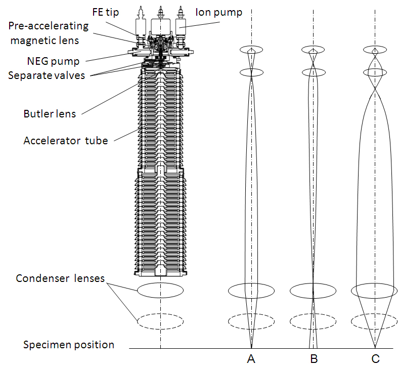
Fig. 1: Schematic view of the illumination system and different ray paths A, B, and C. |
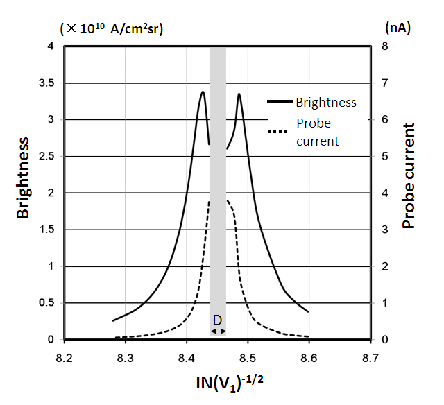
Fig. 2: Calculated brightness and probe current as a function of the excitation of the magnetic lens in terms of IN(V1)-1/2 , where I is the lens current, N is the number of turns of the coil (1700), and V1 is the FE extraction voltage (5 kV). |