MS-7-O-1575 Emission color mapping of white-luminescent mesoporous carbon-silica nanocomposite
Luminescent materials widely used for optical devices, such as light-emitting-diode, plasma display and liquid crystal display rely on the inner-shell transition of rare earth (RE) elements. Unstable RE supply, however, accelerates the importance for developing RE-free luminescent materials. Silicon-oxycarbide (SiOC) has been a promising candidate for white luminescent materials [1], and recently, the present research group found that the mesoporous carbon silica (MPCS) nanocomposite with large surface area emits strong white PL, depending on the degrees of hydrolysis and polycondensation reactions in preparing MPCS [2]. The MPCS nanocomposite consists of a periodic honeycomb silica framework with pores of ~8 nm in diameter.
The synthesis procedures of the MPCS nanocomposite was described in detail elsewhere [3]. The sample was ground by an agate mortar and pestle into fine powder, which was sprinkled on a carbon coated micro-grid. The sample thus prepared was examined using a JEOL JEM-ARM200F STEM (double Cs-corrected) operated at 80 kV and a Gatan Image Filter Quantum ER and an FEI Titan equipped with a Gatan Vulcan TEM-CL system, operated at 80 kV at LN2 temperature for elemental/emission mapping.
Figs. 1(a) and (b) show the side- and top-view of the spatial distributions of silicon/carbon, reconstructed from the STEM-EELS spectrum imaging data sets. As expected, the framework of honeycomb is made of silica, the inner walls of which are covered by amorphous carbon layer. The CL spectrum consists of several emission components (Fig. 2). CL-spectrum imaging scanned along the line shown in Fig. 1(b) revealed that the primary two emission bands (#1 and #2 in Fig. 2) seemed to be derived from the silica frame and inner surface carbon layers, respectively, as shown in Fig. 3. The origin of #2 component is particularly discussed.
References
[1] S. Hayashi, et al, Jpn. J. Appl. Phys. 32 (1993) L274; A. V. Vasin, et al, Jpn. J. Appl. Phys. 46 (2007) L465; S. Y. Seo, K. S. Cho, and J. H. Shin: Appl. Phys. Lett. 84 (2004) 717.
[2] K. Sato, et al, IOP Conf. Ser.: Mater. Sci. Eng. 18 (2011) 102022.
[3] K. Sato, et al, Jpn. J. Appl. Phys. 51 (2012) 082402.
A part of this work was supported by a Grant-in-Aid on Innovative Areas "Nano Informatics" (Grant number 25106004) from the Japan Society of the Promotion of Science.

Fig. 1: HAADF-STEM (Left) and energy filtered image (Right) of MPCS nanocomposite reconstructed by STEM-EELS spectrum image using p-p* plasmon of sp2 carbon (green) and SiO2 volume plasmon (red) respectively for top- (a) and side-view (b). Step width for STEM-EELS ~ 0.5 nm. |
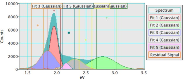
Fig. 2: CL spectrum from MPCS nanocomposite flake, which was fit by 5 gaussians. |
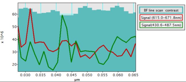
Fig. 3: BF image contrast, #1 and 2 primary emission intensities (cf. Fig. 1) obtained by line scan along the broken line in Fig. 1(b). The red emission (red line) is well correlated with the projected amount of silica, while green emission (green line) with the inner surface of the silica frame. |
|