IT-5-O-1510 Quantitative electron magnetic circular dichroic signals acquired by 1000 kV (S)TEM-EELS
Electron magnetic circular dichroism (EMCD) in EELS is an attractive technique for studying spin-related properties in a higher spatial resolution than the well-utilized x-ray magnetic circular dichroism (XMCD). Even though several effective experimental geometries of the EMCD measurement have been established, these are still substantially in the testing stage due to the intrinsic difficulties associated with quantitative analysis, such as a low signal-to-noise ratio (SNR) and complicated dynamical and plural inelastic scattering effects depending on the sample thickness/orientation. The present study shows the EMCD measurements using a (S)TEM-EELS with an acceleration voltage V of 1000 kV, toward more quantitative local magnetic analysis.
Figure 1 shows the example results of Co L2,3 EELS near edge structures (ELNES) with 200 and 1000 kV acceleration voltages in the intrinsic EMCD method [K. Tatsumi et al., Microcopy, 2014; doi: 10.1093/jmicro/dfu002]. The dichroic signals as the difference spectra showed a better SNR in the 1000 kV case, because of the larger fraction of the dichroic signals.
Figure 2 shows theoretical fractions of the dichroic signals, here represented by a quantity, fd = (IB - IA) / (IA + IB) at the L3 peak energy, as a function of sample thickness t, with several different collection angles φcol represented as EELS aperture radii in units of g shown in Fig. 1. The calculations were performed based on the dynamical diffraction and single core loss scattering. The desirable collection angle is less than 0.2 g because the larger φcol significantly decreases fd. fd at 1000 kV are significantly larger than 200 kV for relatively large thicknesses (t = 30 to 40 nm), because of the larger extinction distance and inelastic mean free path. The simulated and experimental ratios of fd at 1000 kV to fd at 200 kV for t= 35 nm are 2.5 and 3.0, respectively, showing reasonable consistency.
Finally, this advantage is utilized to statistically acquire quantitative EMCD signals distributed over the diffraction plane, demonstrating that quantitative magnetic information can be routinely obtained using electron beams of only a few nanometers in diameter without any restriction regarding the crystalline order of the specimen [S. Muto et al., Nature Commun., 2014; doi: 10.1038/ncomms4138].
This work was partly supported in Grant-in-Aids for Scientific Research of JSPS (Wakate A: 24686070 and Innovative areas: 25106004) and Swedish Research Council.
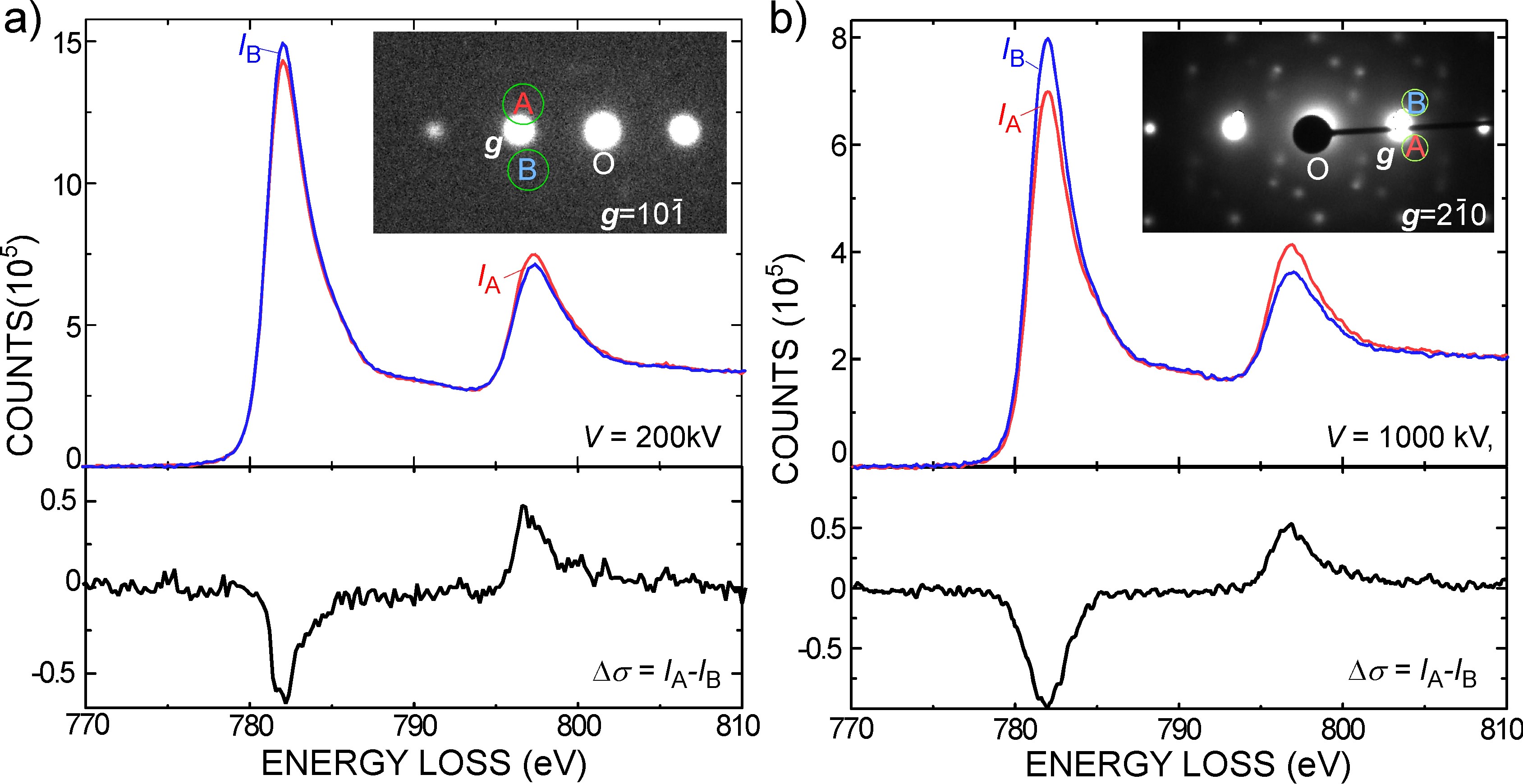
Fig. 1: Experimental Co-L2,3 ELNES collected at two different EELS aperture positions A and B. Two sets of results obtained by using different TEM-EELS systems with different acceleration voltages, 200 kV (a) and 1000 kV (b), are shown. |
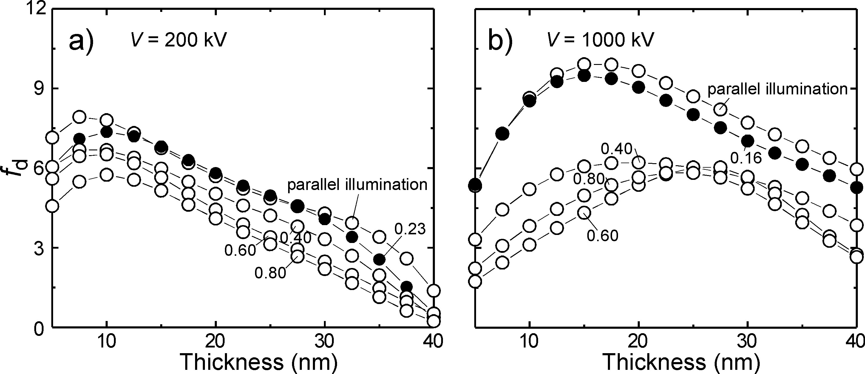
Fig. 2: Theoretical fd with V = 200 and 1000 kV. Numbers inset are φcol, represented by EELS aperture radii in g. Filled circles are results with the experimental φcol. |
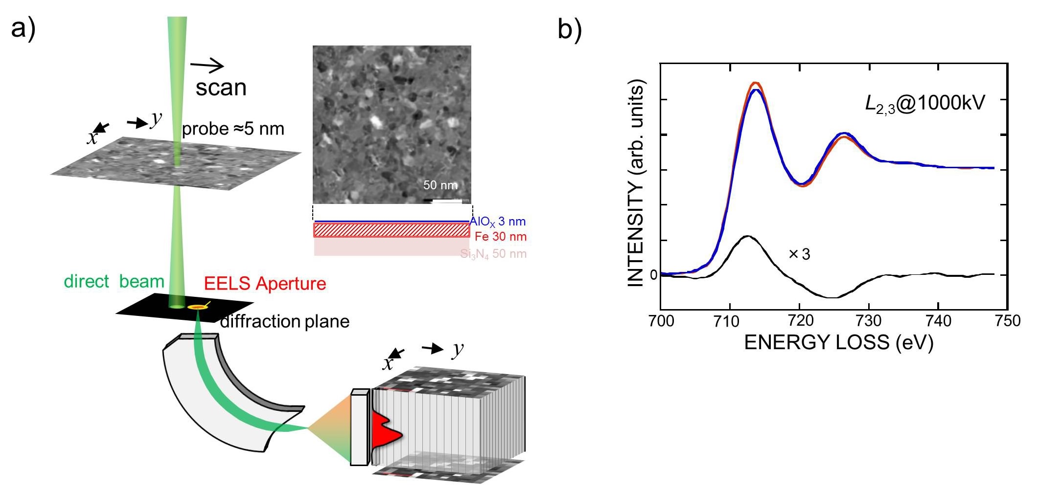
Fig. 3:
|
|